Performance Measurement and Analysis of Non-isolated DC-DC Boost Converter
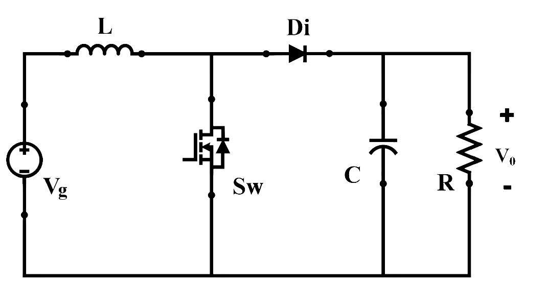
Answer the questions given below (refer Fig.2):

Fig. 2. Circuit configuration of boost converter.
1. When switch (Sw) is in OFF-state, the inductor current:

Fig. 2. Circuit configuration of boost converter.
1. When switch (Sw) is in OFF-state, the inductor current:
2. What will be the voltage across inductor (VL) when diode (Di) is in conducting state?
3. A solar array of 120 V is used to deliver the power to a 400 V DC grid through a boost converter operating at 50 kHz switching frequency. What should be the duty ratio (D1) of boost converter? What will be the required duty ratio (D2) when the switching frequency changes to 100 kHz?
4. A boost converter delivering an output power of 1.0 kW has an efficiency of 92%. Calculate the total losses (PLoss) of the converter.
5. Voltage stress of switch (vSw) and diode (vDi) are :
