
Full Subtractor using 4:1 MUX.
Procedure
Click on 'Full Subtractor using 4:1 MUX' button in Simulation tab.
Follow these steps to perform the experiment:
1. Fill the Truth Table.
2. Click on the component button to place the component.


")
")


Fig. 1: Components
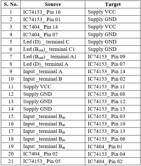
3. To design the full subtractor circuit, use the circuit diagram and pin diagram of the IC or use connection table provided below.
4. Connect outputs D and Bout to LEDs labelled D and Bout respectively.
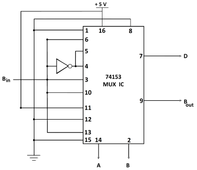
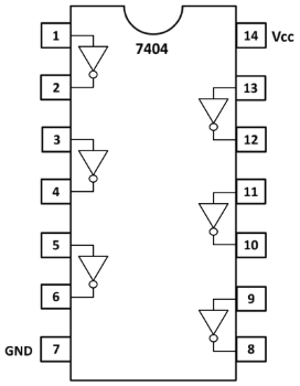
Fig. 2: Circuit diagram of full subtractor using 4:1 MUX. Fig. 3: Pin diagram of NOT-Gate IC-7404.
Table 1: Connection table
5. Once the connections are made, click on 'Check Connections' button. If connections are right, the 'Start Simulation' button will become active. Click on it to start the simulation and use the input toggle switches marked 'A', 'B' and 'Bin' and observe the output.