
Performance measurement and analysis of DC-DC boost regulator
Procedure
a) Circuit formulation (Refer Virtual Experiment Slides):
- Select the correct placement for the highlighted component by “clicking” on the “block”.
- Selection of incorrect block: It becomes RED
- Selection of correct block: Component gets placed
- Repeat the above step for all the components to complete the circuit.
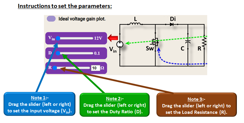
b) Operating the circuit:
- Set the values of Source Voltage (Vin), Load Resistance (R) and Duty Ratio (D).
- Press “RECORD” button to simulate the circuit and observe various waveforms.
- Change “Vin, R and D” to observe the waveforms at different operating conditions.
c) Performance analysis of the circuit:
- Set the values of Source Voltage (Vin), Load Resistance (R) and Duty Ratio (D).
- Select the “ICONS” in sequence to analyse and understand the circuit operation and performance.
- Follow the instructions given in respective experiment slide and press the “RECORD” button to fill the observation table.
