Performance measurement and analysis of DC-DC boost regulator

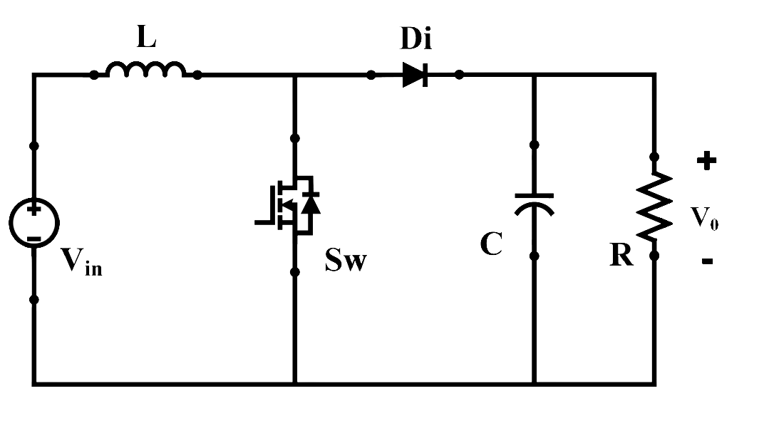
Fig. 2. Circuit configuration of boost converter.
1. When switch (Sw) is in ON-state, the inductor current:
2. What will be the voltage across diode (Di), when switch (Sw) is in OFF-state?
3. An ideal boost converter with 24 V source voltage was operating at a duty ratio of 0.6, after some time it increased to 0.75. What will be the change in the output voltage due to increase in the duty ratio?
4. In a non-ideal boost converter, what is the relationship between the output power (P0) and input power (Pin)?
5. The output voltage of ideal boost converter is 200 V and input voltage is 50 V. The duty ratio required for getting this voltage boosting is:
6. A boost converter has an input voltage of 12 V and an output voltage of 24 V. If the load current is 2A, calculate the average current drawn from the input source assuming ideal conditions (ignore losses).
7. In a boost converter, the switching frequency is 100 kHz, and the duty cycle of the switch is 0.6. Calculate the switch ON (ton) time period.
8. A boost converter operates with an input voltage of 24 V and an output voltage of 48 V. The switching frequency is 50 kHz. Calculate the peak-to-peak current ripple in the inductor if the inductance is 1 mH.
9. In a boost converter circuit, the output voltage is 36 V, and the input voltage is 12 V. The efficiency of the converter is 85%. Calculate the output power if the input current is 5 A.
10. A boost converter has an input voltage of 12 V and an output voltage of 48 V. The converter operates with a switching frequency of 100 kHz. Calculate the duty cycle required for this operation.
