
4-to-16 decoder using 3-to-8 decoder (74138).
Procedure
- Click on the Component button to place components on the table.


")


Fig. 1 Components
- Make connections as per the circuit diagram and pin diagram of ICs or according to connection table.
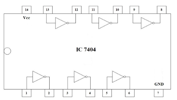
Fig. 2 Circuit Diagram of 4-to-16 decoder
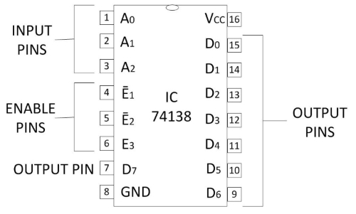
Fig. 3 Pin Diagram of IC 74138
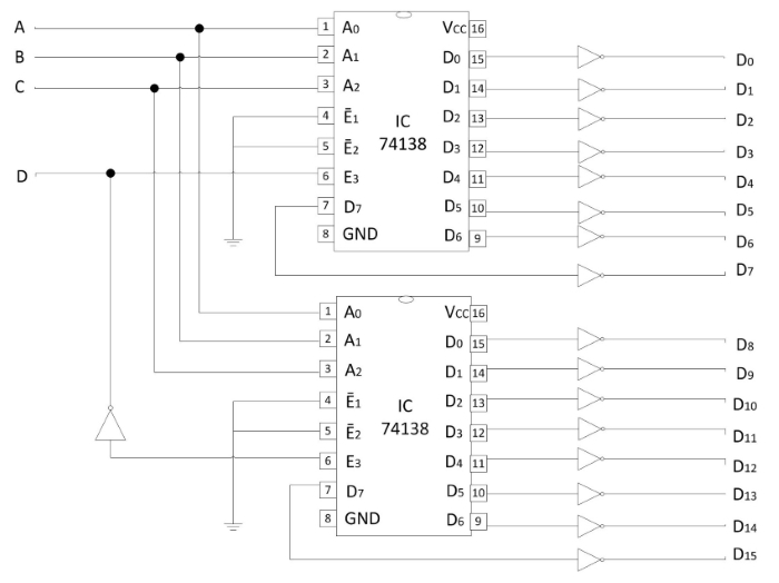
Fig. 4 Pin Diagram of IC 7404

Table 1: Connection table
- Click on Check Connections button. If connections are right, click on ‘OK’, then Simulation will become active.
- Provide the input by clicking toggle switches A, B, C and D.
- Fill the observed values in the Truth Table.
- Verify Truth Table by clicking on Check button, if outputs are correct then click on OK.
- Click on the Reset button to reset the page.