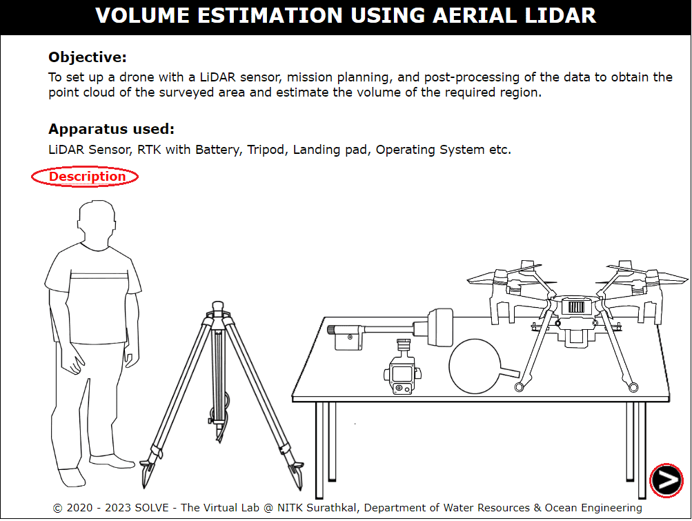
Volume estimation using aerial LIDAR
Begin the simulation by clicking start clicking simulation page. And during the first step all the equipment used for Lidar surveying using UAVs,s can be observed. Continue by clicking the arrow icon at the bottom of the page.
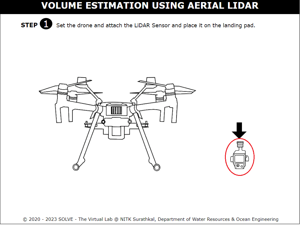
Step 1 shows how the lidar module is attached to the drone, simulation can be achieved by clicking the red circular region below the arrow mark.
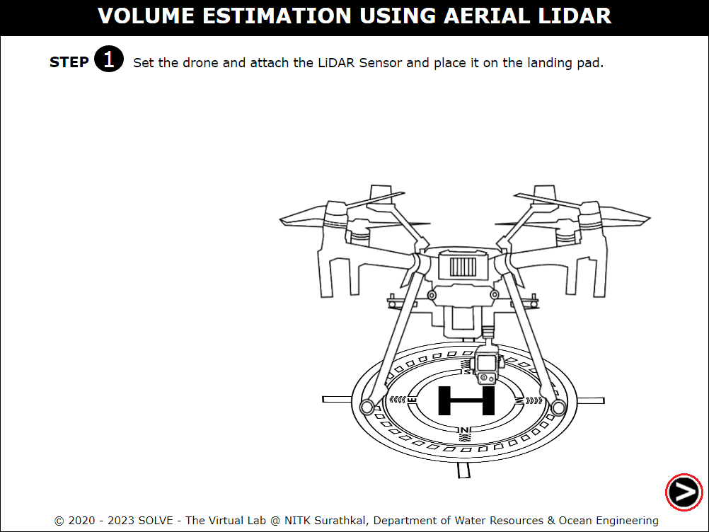
Prepare the UAV for takeoff by placing the UAV on the landing pad in an open sky area. Proceed to the next step by clicking the bottom right arrow symbol.
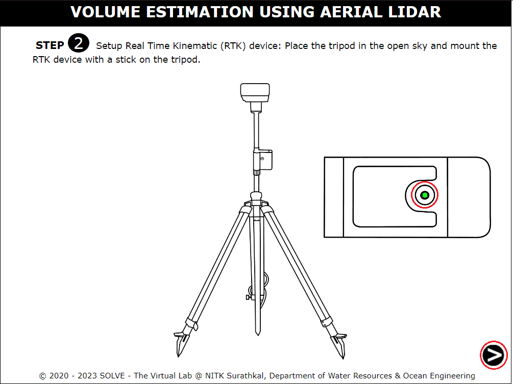
This step shows the setting up of the RTK system by mounting RTK base to the tripod.
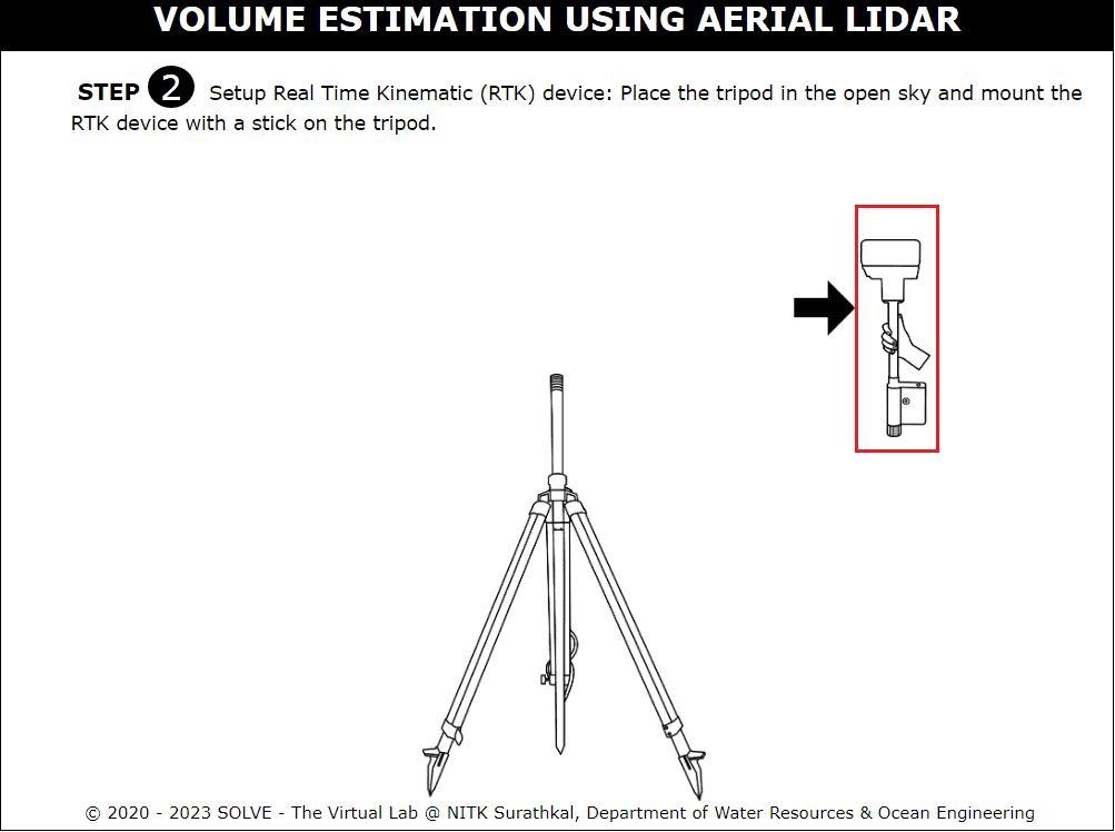
The device has to be leveled perfectly, use a water bubble level to make sure RTK base is in the perfect vertical position. Proceed to the next step by clicking the bottom right arrow symbol.
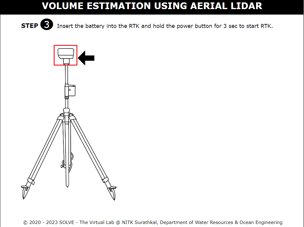
This step shows how the battery can be inserted into RTK base. Proceed to the next step by clicking the bottom right arrow symbol.
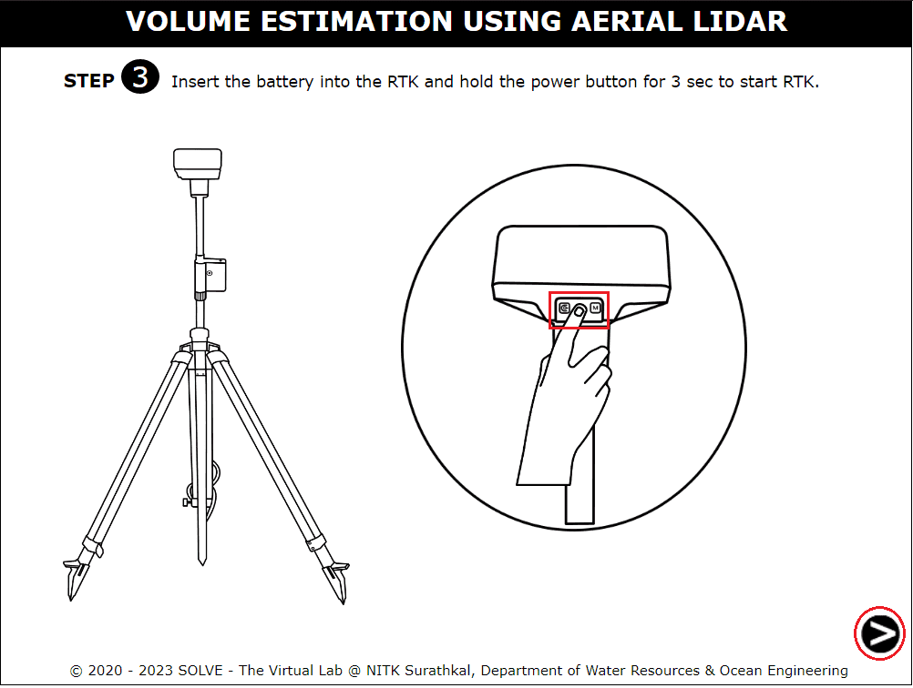
Turn on the RTK base by pressing the middle button for 3 seconds. The red rectangle shows the power button operation. Proceed to the next step by clicking the bottom right arrow symbol.
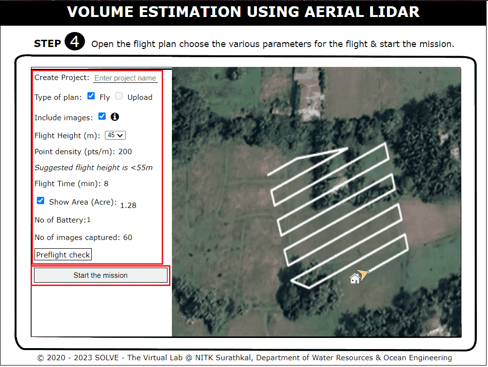
Create a flight plan by entering the project name, selecting relevant parameters, and observing other paraments changing such as flight time. Tick the “show area” region to see flight plan and flight path. Check all preflight check tick marks to enable flying. Click on the start mission button to start the survey.
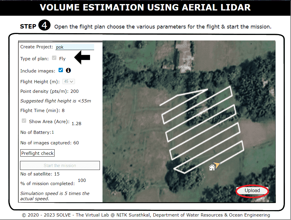
Click on the upload button to start uploading the surveyed scan files region is shown in the red circle. Once loading is completed Proceed to the next step by clicking the bottom right arrow symbol.
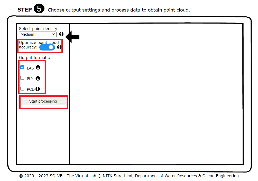
Point cloud output settings can be set on this page by checking various boxes. Each term can be reviewed by hovering the mouse over the “i” icon in front of the parameters. And continue by clicking on the start processing icon. Proceed to the next step by clicking the bottom right arrow symbol after the point cloud is generated.
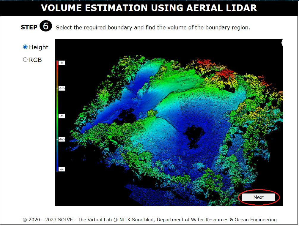
The point cloud can be viewed by either clicking on the Height format or RGB format.
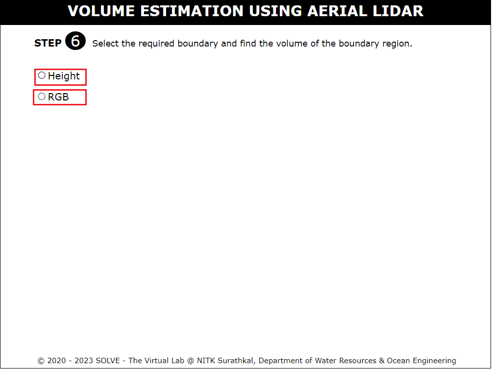
Click the next icon to continue for volume estimation.
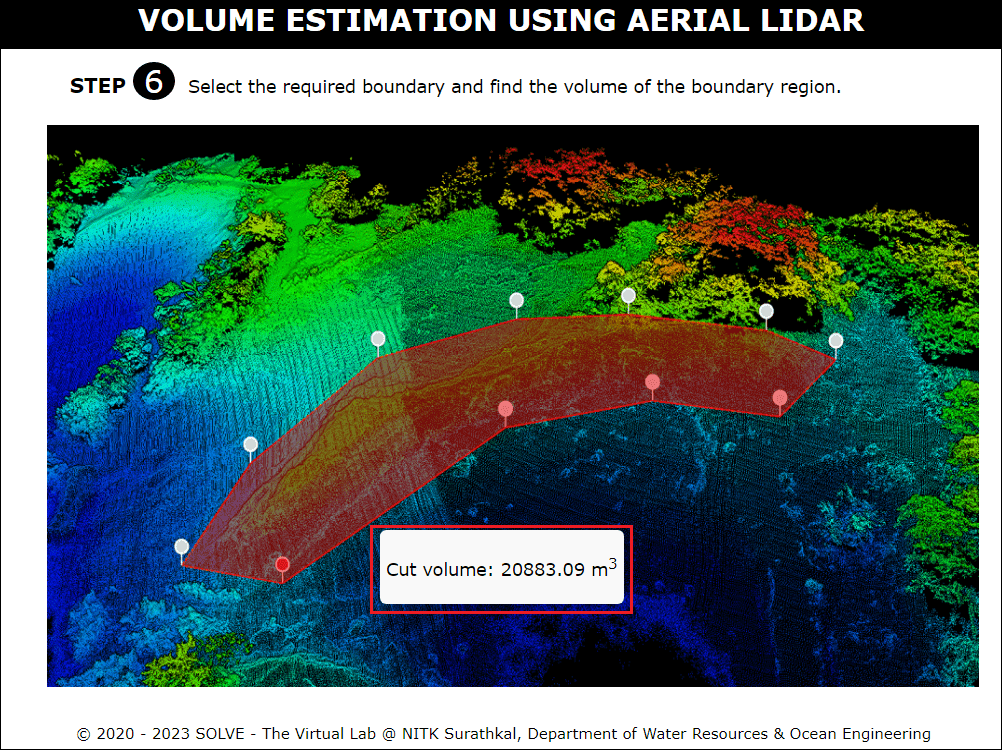
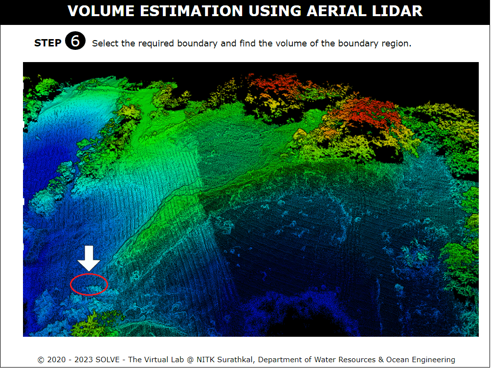
Select the boundary region by clicking below the arrow marks as shown in the simulation.
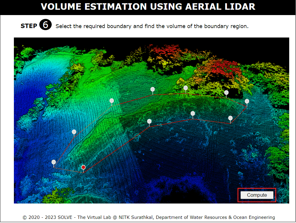
Once the boundary is drawn proceed to compute the volume by clicking the compute icon located in the bottom right corner.
The cut volume or fill volume that is computed will be shown in the final step.