
Unipolar PWM Single Phase Inverter with RL Load
Introduction
SPWM or sinusoidal pulse width modulation is widely used in power electronics to initialize the power so that a sequence of voltage pulses can be generated by the on and off of the power switches. SPWM techniques are characterized by constant amplitude pulses with different duty cycle for each period. The width of these pulses are modulated to obtain inverter output voltage control and to reduce its harmonic content.
Pulse-width modulation (PWM) is a method for reducing the overall harmonic distortion of load current. In general, a PWM inverter output with some filtering can more readily meet THD requirements than a square wave switching system. The unfiltered PWM output will have a reasonably large THD, but the harmonics will be at considerably higher frequencies than for a square wave, making filtering simpler.
With PWM, the modulating waveforms can be used to alter the output voltage's amplitude. PWM has two key advantages: it requires fewer filters to reduce harmonics and lets you alter the output voltage's amplitude. The switches control circuits will need to be more intricate, and switching more frequently will result in higher losses.
The reference signal, also known as a modulating or control signal, in this case a sinusoidal, and the carrier signal, a triangular wave that regulates the switching frequency, are needed to control the switches for sinusoidal PWM output.
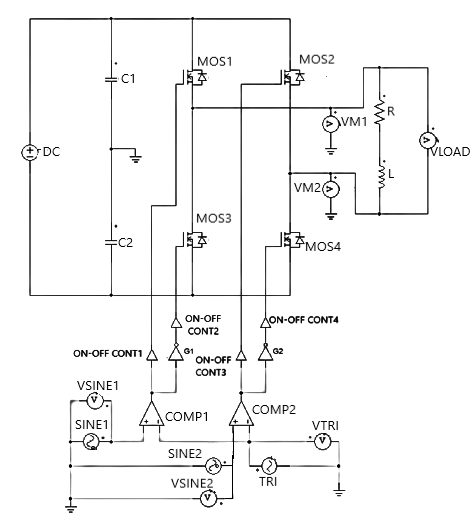
In a unipolar switching scheme for pulse-width modulation, the output is switched either from high to zero or from low to zero, rather than between high and low as in bipolar switching. One unipolar switching scheme has switch controls in Fig. 1 as follows:
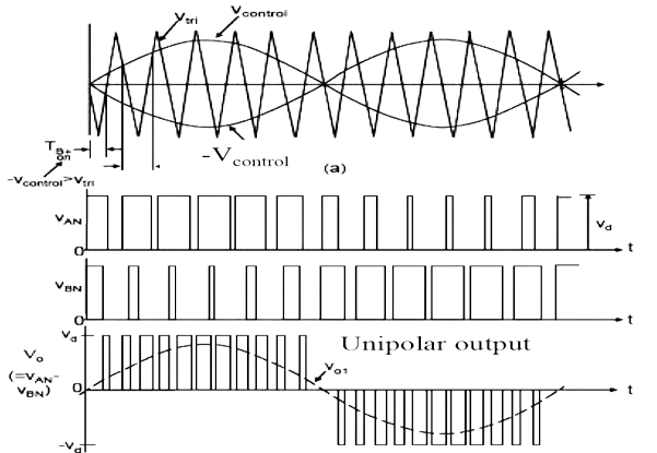
During positive half-cycle, when Vsine is greater than Vtri then Va is Vdc/2 and when Vsine is less than Vtri then Va is -Vdc/2. On the other hand, when -Vsine is greater than Vtri then Vb is Vdc/2 and when -Vsine is less than Vtri then Vb is -Vdc/2. The output voltage across load is 0 when MOS1 & MOS2 or MOS3 & MOS4 are conducting and Vdc when MOS1 & MOS4 are conducting.
During negative half-cycle, when -Vsine is greater than Vtri then Va is Vdc/2 and when -Vsine is less than Vtri then Va is -Vdc/2. On the other hand, when Vsine is greater than Vtri then Vb is Vdc/2 and when Vsine is less than Vtri then Vb is -Vdc/2. The output voltage across load is 0 when MOS1 & MOS2 or MOS3 & MOS4 are conducting and -Vdc when MOS2 & MOS3 are conducting.
If we consider VANref and VBNref to be the modulating signals then
$$v_{o} = V_{o}~sin(w_1t) .......... (1)$$
$$V_{ANref} = \frac {v_{o}}{2V_{dc}} + \frac {1}{2} = \frac {V_o~sin(w_1t)}{2V_{dc}} + \frac {1}{2} .......... (2)$$
$$V_{BNref} = -\frac {v_{o}}{2V_{dc}} + \frac {1}{2} = \frac {-V_{o}~sin(w_1t)}{2V_{dc}} + \frac {1}{2} .......... (3)$$
Frequency modulation ratio (mf): The frequency modulation ratio mf is defined as the ratio of the frequencies of the carrier and reference signals.
$$m_{f} = \frac {f_{tri}}{f_{sine}} .......... (4)$$
Amplitude modulation ratio (ma): The amplitude modulation ratio ma is defined as the ratio of the amplitudes of the reference and carrier signals.
$$m_a = \frac {V_{m}sine} {V_{m}tri} .......... (5)$$
The sinusoidal reference voltage must be generated within the control circuit of the inverter or taken from an outside reference. It may seem as through the function of the inverter bridge is unnecessary because a sinusoidal voltage must be present before the bridge can operate to produce a sinusoidal output. However, there is very little power required from the reference signal. The power supplied to the load is provided by the dc power source, and this is the intended purpose of the inverter. The reference signal is not restricted to a sinusoidal, and other waveshapes can function as the reference signal.
Advantages of Unipolar PWM Single Phase Inverter
- Unipolar PWM control is relatively simple to implement compared to other PWM techniques, such as bipolar PWM. It requires fewer components and circuitry, making it cost-effective and easier to design and construct.
- Unipolar PWM reduces switching losses compared to other PWM techniques. Since the inverter switches are turned on and off only in one polarity, the switching transitions occur at zero voltage, minimizing the power dissipation during these transitions.
- The lower switching losses lead to improved efficiency in the inverter. Reduced power dissipation means less energy is wasted as heat, resulting in higher overall system efficiency.
- Unipolar PWM can help reduce the harmonic distortion in the output waveform. By controlling the pulse width of the output voltage, it is possible to generate a sinusoidal waveform with fewer harmonics, resulting in a cleaner output signal.
- Unipolar PWM can help mitigate electromagnetic interference issues. By reducing the switching transitions and harmonics, the EMI generated by the inverter is minimized, making it suitable for applications with stringent electromagnetic compatibility requirements.
- Unipolar PWM is particularly suitable for voltage source applications, where the DC voltage source remains constant. The unipolar nature of the control scheme simplifies the design and control of the inverter for these applications.
- Unipolar PWM offers a wide control range for adjusting the output voltage. By varying the pulse width, the amplitude of the output voltage can be precisely controlled, allowing for flexible voltage regulation in different load conditions.
Disadvantages of Unipolar PWM Single Phase Inverter
- Unipolar PWM typically results in lower voltage utilization compared to other PWM techniques. Since the inverter switches are operated in a unipolar manner, a portion of the DC voltage source is not utilized effectively, leading to reduced efficiency in converting the DC input to AC output.
- Unipolar PWM may have limitations in achieving a wide output voltage range. The unipolar nature of the control scheme restricts the maximum and minimum voltage levels that can be generated, which may not be sufficient for certain applications requiring a broad range of output voltages.
- Although unipolar PWM can reduce harmonic distortion compared to other modulation techniques, it may still result in higher total harmonic distortion in the output waveform compared to more advanced PWM methods like multilevel PWM. The presence of harmonics can affect the quality of the output voltage and may cause issues with sensitive loads.
- While unipolar PWM can help mitigate electromagnetic interference (EMI) to some extent, it may still generate EMI due to the switching transitions and harmonic content in the output waveform. This can be a concern in applications where EMI compliance is critical or when the inverter is operating in proximity to sensitive electronic equipment.
- Unipolar PWM may have limited control resolution compared to other PWM techniques. The binary nature of the control signal (either fully on or fully off) limits the granularity of control, which may result in less precise voltage regulation and control over the output waveform.
- Unipolar PWM can impose higher stress on the power switching devices (such as MOSFETs or IGBTs) used in the inverter. The abrupt voltage and current transitions during switching can lead to increased switching losses and thermal stress on the devices, potentially affecting their reliability and lifespan.
- Unipolar PWM may not be suitable for all types of loads. Some loads, such as certain motor types or highly capacitive or inductive loads, may require more advanced PWM techniques to ensure proper operation and minimize issues such as torque ripple or power factor distortion.
Applications of Unipolar PWM Single Phase Inverter
- Renewable energy systems
- UPS (Uninterruptible Power Supply)
- Residential and small-scale applications
- Motor control
- Standalone power systems
- Lighting applications
- Research and educational purposes