
Unipolar PWM Single Phase Inverter with RL Load
STEP 1: Drag and drop the components in the workspace to create the circuit.
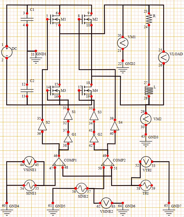
Nos of required components:
DC Source – 1, Capacitor - 2, Mosfet N – 4, Resistor - 1
Inductor – 1, AC Source – 2, Switch – 4, Not Gate- 2
Triangle wave – 1, Comparator - 2, Voltmeter – 6 , Ground – 7
STEP 2: Make the connections as per the instructions given below:
(a) (01-03, 03-06, 06-09, 02-13, 13-16, 16-19)
(b) (04-11, 11-12, 07-15, 10-18, 07-23, 20-23)
(c) (21-22, 23-25, 24-27, 26-28, 18-28)
(d) (28-29, 30-43, 05-35, 14-31, 17-33)
(e) (08-39, 32-37, 38-46 ,36-46, 34-41)
(f) (42-49, 40-49, 47-55, 48-51, 50-57)
(g) (51-58, 58-52, 53-65, 59-65, 55-45)
(h) (44-60, 54-60, 56-61, 57-62, 63-64)
Note: Click on the wire to delete the connection.
STEP 3: Click on the CHECK button to check the connections.
Note: Right click on the component to open the dialog box to edit the properties of the component.
STEP 4: Input the values for all the required components (DC Source, AC Sources, Triangle Source, Capacitors, Resistor and Inductor) and the waveform will get plot automatically.
STEP 5: Now, Click on the ADD button to insert the reading into the observation table.
STEP 6: Now, you can input different values as per your requirement to get the desired waveform.
STEP 7: Repeat Step 5 to again insert the reading into the table and now repeat Steps 6 to 7 to take more readings.
STEP 8: Click on the PRINT button to take out the print of the webpage.
STEP 9: Click on the RESET button to reload the webpage.