
Three Phase Half Wave Silicon Controlled Rectifier with R Load and RL Load
Introduction
A three-phase half-wave controlled rectifier is an electrical circuit used for converting alternating current (AC) into direct current (DC) by controlling the flow of current through a load. It is called a half-wave rectifier because it rectifies only one half of the input waveform.
Here's an explanation of the working principle of a three-phase half-wave controlled rectifier:
Input: The rectifier is connected to a three-phase AC power source. The AC voltage waveform consists of three phases: phase A, phase B, and phase C.
Rectification: Each phase of the AC source is connected to a thyristor, forming a thyristor bridge. The diodes allow current flow in one direction and block it in the other direction. When the input voltage is positive in one phase, the corresponding thyristor conducts provided that gate trigger is given, allowing current to flow through the load connected to the output side of the bridge.
Control: In a controlled rectifier, the current flow through the thyristor (also known as a silicon-controlled rectifier or SCR). The thyristor acts as a switch that can be turned on or off depending on the control signal applied to its gate.
Triggering: To control the rectification process, the thyristors are triggered at specific points in the input waveform. Triggering is achieved by applying a pulse signal to the gate of the thyristor at the desired firing angle. The firing angle determines the portion of the input waveform during which the thyristor conducts current.
Conduction: Once triggered, the thyristor turns on and allows current to flow through the load until the end of the half-cycle or until the thyristor is turned off.
Commutation: When the input waveform crosses zero or becomes negative, the natural commutation occurs, turning off the conducting thyristor. This happens because the forward voltage across the thyristor drops below its holding voltage.
Output: The load connected to the output of the rectifier receives a pulsating DC voltage, which consists of positive half-cycles. The output voltage waveform is the result of rectifying only one half of the input waveform.
By controlling the firing angle of the thyristors, the average output voltage can be varied, enabling the regulation of power delivered to the load.
It's important to note that the three-phase half-wave controlled rectifier is a simplified configuration and may require additional components, such as filters and smoothing capacitors, to reduce ripple and provide a smoother DC output. Overall, the three-phase half-wave controlled rectifier provides a means to convert three-phase AC power to pulsating DC power by controlling the firing of thyristors in each phase.
1. Three Phase Half Wave Controlled Rectifier - R Load
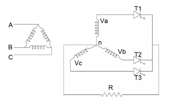
The circuit consist of a delta star transformer and 3 thyristors T1, T2, T3 which are connected on the secondary star connected winding and a resistive load.
When a Va is positive, T1 becomes forward biased and conducts. During the negative cycle of Va, T1 turns off.
Similarly T2 and T3 conducts only during the positive cycles of Vb and Vc respectively.
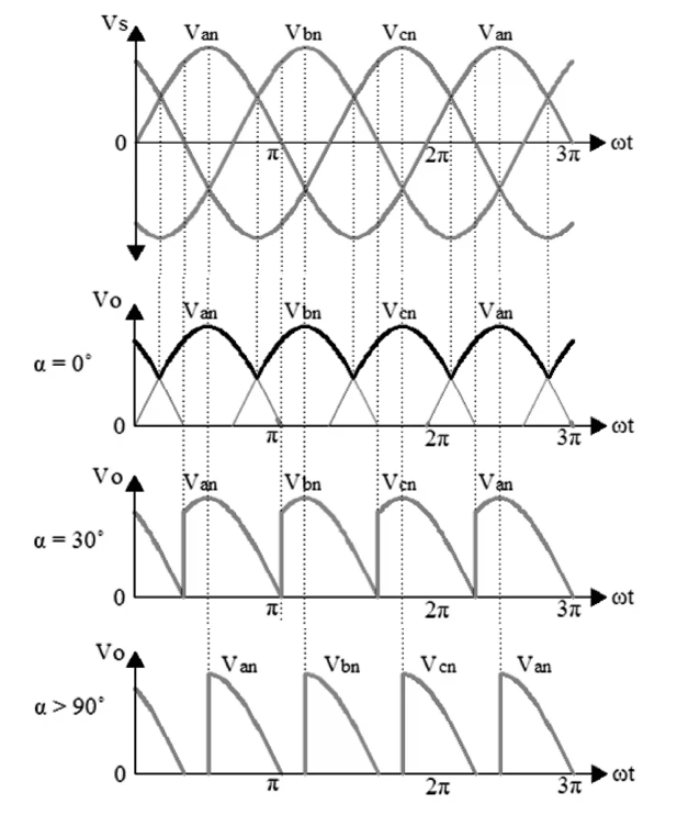
The average output voltage can be varied by varying the firing angles of the thyristors. The waveforms show the output voltage for various firing angles.
In the waveform, Va is denoted as Van, Vb as Vbn and Vc as Vcn.
The expression for average and rms of output voltage and current are,
For α < 30°
$$V_{o} = \frac {1}{\frac {2\pi}{3}} \int_{\alpha+\frac {\pi}{6}}^{\alpha+\frac {5\pi}{6}} V_{mp}\ sinwt ~ dwt = \frac {3\sqrt 3}{2\pi}V_{mp}\cos\alpha = \frac {3}{2\pi}V_{ml}\cos\alpha.......(1)$$
$$I_{o}= \frac {V_{o}}{R} = \frac {3}{2\pi R}V_{ml}\cos\alpha.......(2)$$
$$V_{o~(rms)} = \left[ \frac {1}{\frac {2\pi}{3}} \int_{\alpha+\frac {\pi}{6}}^{\alpha+\frac {5\pi}{6}} V_{mp}^2\ sin^2wt\ dwt \right]^{1/2}$$
$$V_{o~(rms)} = \sqrt {3} V_{mp} \left[ \frac {1}{6} + \frac {\sqrt {3}}{8\pi} cos2\alpha \right]^{1/2} = V_{ml} \left[ \frac {1}{6} + \frac {\sqrt {3}}{8\pi} cos2\alpha \right]^{1/2}.......(3)$$
$$I_{o(rms)} = \frac {V_{o(rms)}}{R} = \frac {\sqrt {3} V_{mp}}{R} \left[ \frac {1}{6} + \frac {\sqrt {3}}{8\pi} cos2\alpha \right]^{1/2}.......(4)$$
For α > 30°
$$V_{o} = \frac {1}{\frac {2\pi}{3}} \int_{\alpha+\frac {\pi}{6}}^{\pi} V_{mp}\ sinwt\ dwt = \frac {3}{2\pi}V_{mp} \bigg[1+cos(\alpha+30^{\circ})\bigg] ......(5)$$
$$I_{o} = \frac {V_{o}}{R} = \frac {3}{2\pi R} V_{mp} \bigg[1+cos(\alpha+30^{\circ}) \bigg] .......(6)$$
$$V_{o~(rms)} = \left[ \frac {1}{\frac {2\pi}{3}} \int_{\alpha+\frac {\pi}{6}}^{\pi} V_{mp}^2\ sin^2wt\ dwt \right]^{1/2}$$
$$V_{o~(rms)} = \frac {\sqrt {3} V_{mp}}{2\sqrt {\pi}} \left[ \left(\frac {5\pi}{6} - \alpha \right) + \frac {1}{2} sin(2\alpha + \frac {\pi}{3})\right]^{1/2}.......(7)$$
$$I_{o~(rms)} = \frac {V_{o(rms)}}{R} = \frac {\sqrt {3} V_{mp}}{2\sqrt {\pi}R} \left[ \left(\frac {5\pi}{6} - \alpha \right) +\frac {1}{2} sin(2\alpha + \frac {\pi}{3})\right]^{1/2}.......(8)$$
2. Three Phase Half Wave Controlled Rectifier - RL Load
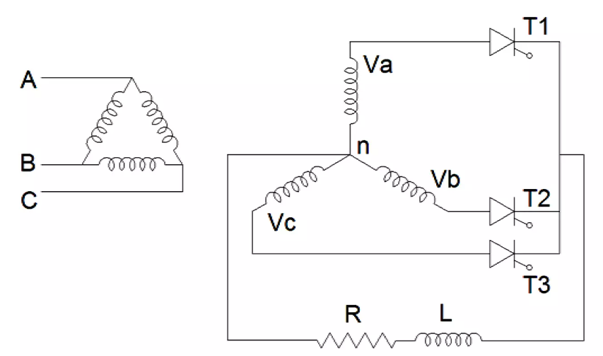
The circuit consist of a delta transformer and 3 thyristors T1, T2, T3 which are connected on the secondary star connected winding and a RL load.
When Va is positive, T1 becomes forward biased and conducts. During the negative cycle of Va, the current through T1 is not zero due to inductor
present in the load. So T1 will remian ON during the negative cycle of Va. When Vb is positive, T2 is triggered and the load current gets transferred
from T1 to T2. At this instant, T1 turns OFF. During the negative cycle of Vb, the current through T2 is not zero due to inductor present in the load.
So T2 will remain ON during the negative cycle of Vb. When T3 is triggered during positive cycle of Vc, the load current is transferred from T2 to T3.
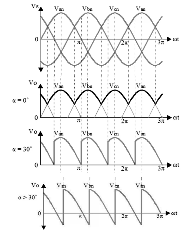
At this instant, T2 turns OFF. Similarly, T3 conducts during the negative cycle of Vc and turns OFF when T1 is triggered. The average output voltage can be varied by varying the firing
angles of the thyristors. The waveforms shows the output voltage for various firing angles. In the waveform, Va is denoted as Van, Vb as Vbn, Vc as Vcn.
The average and rms of bridge output voltage and current is,
$$V_{o} = \frac {1}{\frac {2\pi}{3}} \int_{\alpha+\frac {\pi}{6}}^{\alpha+\frac {5\pi}{6}} V_{mp}\ sinwt\ dwt = \frac {3\sqrt 3}{2\pi}\ V_{mp}\ cos\alpha = \frac {3}{2\pi}\ V_{ml}\ cos\alpha.......(9)$$
$$I_{o} = \frac {V_{o}}{R} = \frac {3}{2\pi R}\ V_{ml}\ cos\alpha.......(10)$$
$$V_{o~(rms)} = \left[ \frac {1}{\frac {2\pi}{3}} \int_{\alpha+\frac {\pi}{6}}^{\alpha+\frac {5\pi}{6}} V_{mp}^2\ sin^2wt\ dwt \right]^{1/2}$$
$$V_{o~(rms)} = \sqrt {3} V_{mp} \left[ \frac {1}{6} + \frac {\sqrt {3}}{8\pi} cos2\alpha \right]^{1/2} = V_{ml} \left[ \frac {1}{6} + \frac {\sqrt {3}}{8\pi} cos2\alpha \right]^{1/2}.......(11)$$
$$I_{o(rms)} = \frac {V_{o(rms)}}{R} = \frac {\sqrt {3} V_{mp}}{R} \left[ \frac {1}{6} + \frac {\sqrt {3}}{8\pi} cos2\alpha \right]^{1/2}.......(12)$$
Advantages of Three Phase Half Wave SCR
Three-phase rectifiers are known for their high efficiency in converting AC power to DC power. The half-wave controlled rectifier configuration allows for efficient power conversion by utilizing only half of the AC input waveform, resulting in reduced power loss.
Reduced ripple content: The three-phase input of the rectifier provides a more continuous and balanced waveform, resulting in reduced ripple content in the output DC voltage. This leads to improved output voltage stability and reduced voltage fluctuations, which is beneficial for applications that require a steady DC supply.
Three-phase rectifiers inherently have lower harmonic distortion compared to single-phase rectifiers. The balanced three-phase input waveform helps to minimize the generation of harmonics, which can cause interference and inefficiency in electrical systems. Lower harmonic distortion contributes to improved power quality and reduced stress on the electrical components.
Three-phase systems are capable of delivering higher power compared to single-phase systems. The three-phase half-wave controlled rectifier can handle larger power loads, making it suitable for applications that require high-power DC supplies, such as industrial motor drives, power supplies for electric vehicles, and large-scale battery charging systems.
The use of three-phase power distribution provides redundancy and improved reliability in electrical systems. In case of a fault or failure in one phase, the other two phases can continue to deliver power, ensuring uninterrupted operation. This increased reliability is crucial for critical applications where downtime can be costly.
Three-phase rectifiers offer better power factor correction capabilities compared to single-phase rectifiers. Power factor correction helps to reduce reactive power and improve the overall power efficiency of the system. By utilizing three-phase power, the rectifier can achieve improved power factor performance, resulting in reduced electricity consumption and improved energy efficiency.
Disadvantages of Three Phase Half Wave SCR
The half-wave controlled rectifier can only utilize half of the input waveform, resulting in a lower average output voltage compared to full-wave rectifiers. This reduces the overall efficiency of the rectification process.
The rectified output waveform of a half-wave controlled rectifier contains significant harmonic distortion. This can lead to increased electromagnetic interference (EMI) and reduced power quality in the electrical system.
The rectifier draws current from the AC supply discontinuously, causing a poor power factor. This can result in increased line losses and decreased overall system efficiency. Power factor correction techniques may be necessary to compensate for this drawback.
The half-wave controlled rectifier is not suitable for driving inductive loads, such as motors, due to its intermittent output waveform. Inductive loads require a continuous and smooth DC voltage for proper operation. This limitation restricts its applicability in many industrial and power system applications.
The output voltage of the rectifier is influenced by changes in the input voltage, load impedance, and firing angle control. Achieving precise voltage regulation can be challenging, especially when operating with varying load conditions.
The use of power electronic devices like thyristors or diodes in the rectifier circuit exposes them to high-voltage transients during switching operations. This can lead to increased stress on these components, potentially reducing their reliability and requiring additional protective measures.
The control circuitry required for managing the firing angle of the rectifier adds complexity to the overall system design. It requires additional control and feedback mechanisms to achieve proper operation, making it more intricate and potentially more expensive to implement.
The combination of low output voltage, poor power factor, and increased harmonic content results in reduced overall efficiency for the half-wave controlled rectifier compared to other rectifier topologies. This can lead to increased power losses and energy wastage.
Applications of Three Phase Half Wave SCR
Motor Drives
Welding Equipment
Power Quality Control
Battery Charging Systems
Power Supplies