
Step-down Chopper with R Load
Introduction
A Step-down Chopper, also known as a Buck Chopper, is an electronic circuit used to control the output voltage of a DC power source to a lower level. It is commonly used in applications where a variable or reduced DC voltage is required,
such as in battery charging systems, voltage regulators, or motor speed control. The basic working principle of a Step-down Chopper involves the periodic switching of a semiconductor switch (usually a transistor) to control the output voltage. The chopper
operates in a time-varying ON-OFF mode, where the switch turns ON and OFF repeatedly at a certain frequency.
Working Principle of Step-down Chopper
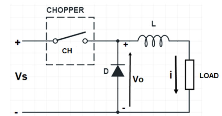
To understand the working principle, let us first have a look at an equivalent circuit diagram of step-down chopper. This is shown in Fig. 1. The chopper is shown within a dotted line and assumed to be a switch. This circuit consists of inductor L, a free-wheeling diode, chopper CH, Source and Load. Fixed DC input voltage Vs is applied and our aim is to get the variable DC output voltage which is a function of chopper. To get the variable DC voltage, we will switch ON and OFF the chopper CH at some frequency called the chopping frequency (f).
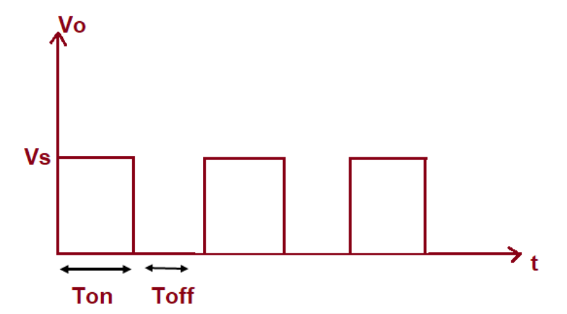
When Chopper CH is switched ON: When CH is switched ON, the source is directly connected to load and hence the output voltage Vo becomes equal to Vs. The time period for which chopper is kept ON is called ON Time of chopper and represented by TON. Thus, Vo will be equal to Vs for time TON. The waveform of output voltage and time is shown in figure below.
During the ON period of chopper, the current will build in the load exponentially and will reach its maximum value at the end of TON (It is assumed that TON is less than the time required for load current to reach its steady state value). This, simply means that the maximum value of load current io will be less than the steady state value. The waveform of load current and time of step-down chopper is shown in figure below.
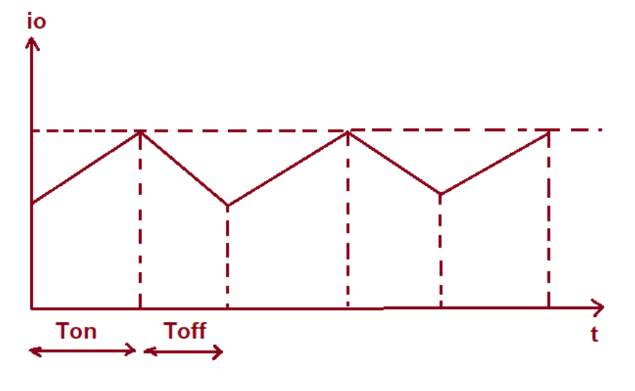
In the above figure, the load current during TON time is shown linearly increasing with time. This is because the chopping frequency is high and hence TON is very less. For a small time period, the exponential rise of current may be approximated to the linear rise.
When Chopper CH is switched OFF: When chopper in Fig. 1 is switched OFF, the load is disconnected from the source Vs and hence load voltage Vo will be zero during the entire period for with CH is OFF. The time for which chopper is kept OFF is known as OFF time and represented by TOFF, the current through the inductor L (io) cannot suddenly drop to zero. Rather, it starts decreasing and hence the polarity of induced emf across the inductor reverses, This induced emf of inductor makes free-wheeling diode forward biased and hence, free-wheeling diode (D) acts as a short during TOFF. Thus, the load current continues to decay through inductor L, free-wheeling diode D and load even though the source Vs is disconnected as shown in Figure 3. The load current reaches its minimum value during OFF time and then CH is again switched ON.
Derivation of Average Output DC Voltage
To find the average output DC voltage, carefully observe the Vo vs time waveform shown earlier and notice that Vo is equal to Vs for TON time and is zero for TOFF time. As we know that average value of any periodic function f(x) with time period T is given as below.
$$\frac {1}{T} \int_0^T f(x) ~ dx......(1)$$
Therefore, using the above formula we can easily find the value of average value of output voltage of Step-down chopper.
It should be noted that the time period of chopper DC Output Voltage Waveform is T = TON + TOFF. The formula for output voltage of chopper is
$$V_o = \frac {1}{T} \int_0^{T_{ON}} V_s. dt + \int_0^{T_{OFF}} 0.dt$$
$$V_o = \frac {V_s.T_{ON}}T......(2)$$
Since, duty cycle α given by
$$α= \frac {T_{ON}}{T}......(3)$$
$$V_o = α.V_s......(4)$$
Output current is given by
$$i_o = \frac {α.V_s}{R}......(5)$$
The rms output voltage is
$$V_{rms} = \sqrt \frac {1}{T} \int_0^{T_{ON}} V_s^2. dt = V_s \sqrt \frac{T_{ON}}{T}$$
$$V_{rms} = V_s* \sqrt α......(6)$$
From the above formula, it can be concluded that the output voltage of step-down chopper can be varied from zero to source voltage Vs, This is achieved by varying the duty cycle (α).
Advantages of Step-down Chopper
1. Voltage Reduction: The primary advantage of a step-down chopper is its ability to reduce the output voltage from a higher level to a lower level efficiently. This feature is valuable in applications where the input voltage exceeds the requirements of the load or system.
2. Efficiency: Step-down choppers can achieve high conversion efficiency, especially when operating in Continuous Conduction Mode (CCM). By storing and transferring energy through the inductor, the chopper minimizes energy losses during the conversion process.
3. Regulation and Control: Step-down choppers allow for precise regulation and control of the output voltage. By adjusting the duty cycle of the chopper's switch, the output voltage can be varied as needed to match the load requirements.
Disadvantages of Step-down Chopper
1. Higher Component Stress: In step-down choppers, the inductor and switch experience higher current stresses, especially during the switch turn-on phase. This may require the use of components with higher current ratings, which can impact cost and design complexity.
2. Complexity: Step-down choppers involve rapid switching of the components, leading to switching losses. Minimizing these losses requires careful selection of switching devices and optimization of control strategies.
3. Electromagnetic Interference (EMI): The fast switching action of step-down choppers can lead to electromagnetic interference (EMI) generation, which may require additional filtering and shielding measures to comply with electromagnetic compatibility (EMC) standards.
Applications of Step-down Chopper
1. DC Motor Speed Control: Step-down choppers are commonly used in DC motor speed control applications. By reducing the voltage supplied to the motor, the chopper can control the motor's speed and torque output.
2. Battery Charging: Step-down choppers are utilized in battery charging circuits, especially for charging lithium-ion and lead-acid batteries. They regulate the charging voltage to match the battery's requirements.
3. DC-DC Buck Converters: Step-down choppers serve as the foundation for DC-DC buck converters, which are widely used in power supply circuits to provide lower output voltages for electronic devices and systems.
4. Voltage Regulation in Power Supplies: Step-down choppers, also known as buck converters, are widely used in power supply circuits to regulate the output voltage. They efficiently reduce a higher input voltage (from the mains or a DC source) to a lower, stable voltage suitable for powering electronic devices such as microcontrollers, integrated circuits, and sensors.