Determination of stacking fault energy in FCC alloys
Several experimental techniques can be used to determine the stacking fault energy in FCC alloys using TEM and XRD techniques.
A. Transmission electron microscopy (TEM)
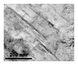
TEM is a powerful technique for directly observing the stacking faults at the atomic scale due to its high resolution. The contrast from the stacking faults can be observed directly under the microscope. The separation between the partial dislocations can be measured and then the following equation is employed for the calculation SFE:

Here, G is the shear modulus, b is the Burgers vector of the partial dislocations, ν is the Poissons ratio and r and r0 are characteristic radii.

B. X-ray diffraction (XRD)
XRD can also be employed to estimate the SFE by analysing the broadening of the diffraction peaks. Sfe is estimated from the stacking fault probability using an empirical relationship. For the determination of SFE using the XRD technique, the Reed and Schramm equation is commonly used for FCC materials:

here, G111 is the shear modulus in the <111> direction, a0 the lattice parameter, <ε2111> the mean square strain in the <111> direction, PSF the stacking fault probability and the A is the correction factor accounting for elastic anisotropy.
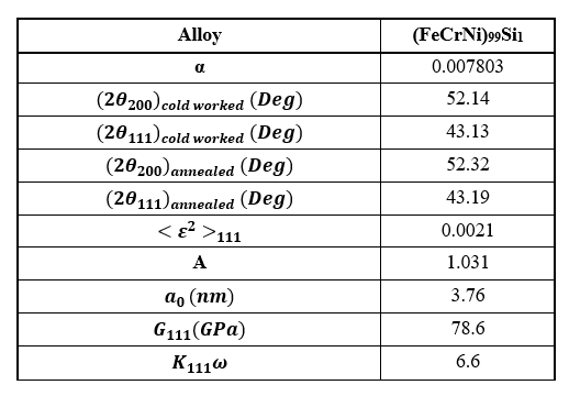
The XRD micro strain method was employed to estimate the SFE for FeCrNi99Si1[1]. The PSF is stacking fault probability (SFP). The SFP was calculated using the following formula:

A is Zener anisotropy, calculated using following formula:

The following table contains the values considered for the estimation. All the values considered for the SFE estimation using XRD microstrain technique for
FeCrNi99Si1[1].

C. Thermodynamic Calculations
The calculation of SFE in the FCC matrix can also be done using thermodynamic calculations:

here ρ is the molar surface density along <111> direction, ΔGγ->ε the Gibbs free energy difference between the FCC and HCP matrix, and σγ->ε is the interfacial energy of the γ/ε interface. The value of ΔGγ->ε is given by the Olsen-Cohen equation:

here, xi is the molar fraction of components, ΔGγ->εi the Gibbs free energy difference of FCC and HCP-martensite phase, Ωγ->εij the Gibbs free energy difference of FCC and HCP is the binary system. ΔGγ->εmg is the magnetic contribution to Gibbs free energy difference and ΔGγ->εseg(int) is the Gibbs free energy due to the segregation of alloying elements.
