
Performance measurement and analysis of 1-phase IGBT inverter with sinusoidal PWM control
Answer the questions given below (refer Fig.1):
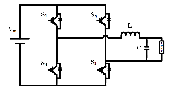
Fig. 1. Circuit diagram of single-phase bridge inverter.
1. In a single-phase inverter, at any given instant how many switches are turned - ON?
Fig. 1. Circuit diagram of single-phase bridge inverter.
1. In a single-phase inverter, at any given instant how many switches are turned - ON?
2. What is output voltage when switch “S2” and “S4” are turned “ON”
3. Inverter converts
4. In single-phase inverter, gate pulse is available for switches “S1” and “S2” when
5. The Total Harmonic Distortion (THD) is