
Performance measurement and analysis of 1-phase IGBT inverter with sinusoidal PWM control
Answer the questions given below (refer Fig.2):
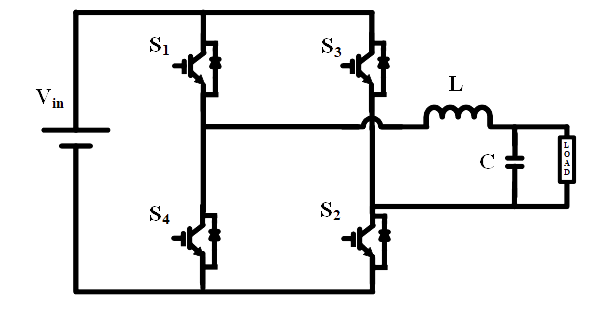
Fig. 2. Circuit diagram of single-phase bridge inverter.
1. In a single-phase bridge inverter, which of the switches are in ON-state when the output voltage is “+Vin”’
Fig. 2. Circuit diagram of single-phase bridge inverter.
1. In a single-phase bridge inverter, which of the switches are in ON-state when the output voltage is “+Vin”’
2. The single-phase bridge inverter is fed from 48 V DC supply and its load resistance is 2.4 Ω. The rms value of fundamental component of output voltage is
3. In a single-phase inverter, which harmonic component is not present
4. A single-phase bridge inverter driven with sinusoidal PWM. The reference waveform frequency (fr) is 50 Hz while the carrier frequency (fc) is 10 kHz. The number of pulses per half cycle of the output voltage waveform will be
5. A single-phase bridge inverter having square wave output of pulse width 180o has the DC supply of 60 V. The rms value of output voltage is