
Single phase IGBT inverter under sinusoidal PWM control
Answer the questions given below (refer Fig.2):
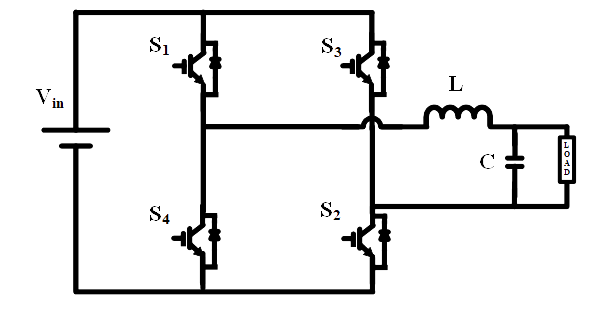
Fig. 2. Circuit diagram of single-phase bridge inverter.
1. In a single-phase bridge inverter, when the output is ‘-Vin’
Fig. 2. Circuit diagram of single-phase bridge inverter.
1. In a single-phase bridge inverter, when the output is ‘-Vin’
2. In single-phase inverter, gate pulse is available for switches “S1” and “S2” when
3. A multi-pulse PWM scheme is used to drive the switches of a single-phase bridge inverter. If ‘Vdc’ is the inverter input voltage, the rms value of load voltage is given by
4. A single-phase bridge inverter driven with sinusoidal PWM. The reference waveform frequency (fr) is 50 Hz while the carrier frequency (fc) is 5 kHz. The number of pulses per half cycle of the output voltage waveform will be
5. A single-phase bridge inverter with multiple pulse width modulation (MPWM) has a DC voltage source of 230 V and modulation index (MI) 0.5. What is the rms value output voltage?