
Single Phase Half Wave Silicon Controlled Rectifier with R Load, RL Load & RLE Load
Introduction
Single Phase Half Wave Controlled Rectifier is a rectifier circuit which converts AC input into DC output only
for positive half cycle of the AC input supply. The word “controlled” means that, we can change the starting
point of load current by controlling the firing angle of SCR, the SCR turn ON at certain point of time when it
is forward biased.
A Single Phase Half Wave Controlled Rectifier circuit consists of SCR / thyristor, an AC voltage source and
load. The load may be purely resistive, Inductive or a combination of resistance and inductance.
Following points must be kept in mind while discussing controlled rectifier:
- The necessary condition for turn ON of SCR is that, it should be forward biased and gate signal must be
applied. In other words, an SCR will only get turned ON when it is forward biased and fired or gated.
- SCR will only turn off when current through it reaches below holding current and reverse voltage is applied
for a time period more than the SCR turn off time.
1. Single Phase Half Wave Controlled Rectifier with Resistive Load
A logarithmic amplifier is an electronic circuit that produces an output that is proportional to the logarithm of the applied input. An op-amp based logarithmic amplifier produces a voltage at the output, which is proportional to the logarithm of the voltage applied to the resistor connected to its inverting terminal. The circuit diagram of op-amp based logarithmic amplifier is shown in figure 1.
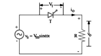
The circuit is energized by the line voltage or transformer secondary voltage, V = Vm sin ωt as
shown in Fig 1. Here, V0 = Load output voltage, i0 = Load current and VT = Voltage across the thyristor T. It is assumed that the peak supply voltage never exceeds the forward and reverse-blocking ratings of the thyristor. The thyristor can be triggered at any angle α in the positive half cycle and thus the output voltage can be controlled. The thyristor blocks during the negative half cycle. The various voltage and current waveforms for the Single Phase Half Wave Controlled Rectifier with resistive load circuit are shown in Fig 2.
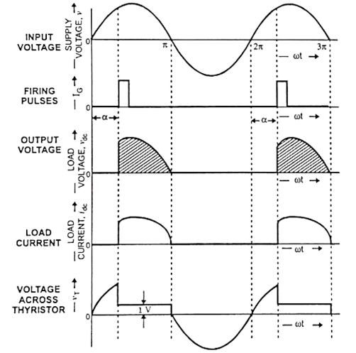
During the positive half cycle of the supply voltage, the thyristor anode is positive w.r.t, its cathode and
until the thyristor is triggered by a proper gate pulse, it blocks the flow of load current in the forward
direction.
When the thyristor is fired at an angle α, full supply voltage (ignoring the thyristor drop VT) is
applied to the load. Thus, the load is directly connected to the ac supply. With a zero reactance source and a
purely resistive load, the current waveform after the thyristor is triggered will be identical to the applied
voltage wave and of a magnitude dependent on the amplitude of the applied voltage and the value of the load
resistance R. At zero crossing, the thyristor is turned off by natural commutation thereby switching off the
power to the load. The voltage and current are in same phase, as illustrated in Fig. 2. The angle (π – α)
during which the thyristor conducts is called the conduction angle. By varying the firing angle α, the output
voltage can be controlled. During the period of conduction, voltage drop across the thyristor is of the order
of one volt. During the negative half cycle of the supply voltage, the thyristor blocks the flow of load
current and no voltage is applied to the load R.
Analysis : Average load voltage is given by
$$V_{dc} = \frac {1}{2\pi} \left[\int_{\alpha}^{\pi} V_m ~ sin ~ \omega t ~ d(\omega t)+\int_{\pi}^{2\pi}(0)~d(\omega t)\right]$$
$$V_{dc} = \frac {1}{2\pi} \bigg[-V_m ~ cos\omega t \bigg]_{\alpha}^{\pi} = \frac {V_m}{2\pi}(1+cos \alpha)........(1)$$
Where, Vm is peak value of the ac input voltage.
From the above Eq. (1) it is obvious that the load voltage varies with firing angle α having extremes values
for α = 0 and α = π or 180°. The maximum output voltage is obtained when α = 0 and is given by
$$V_{dc ~ max} =\frac {V_m}{\pi} .......(2)$$
Average load current with resistive load is directly proportional to the average load voltage and is given by
$$I_{dc} = \frac {V_{dc}}{R} = \frac {V_m}{2\pi R}(1+cos \alpha ).......(3)$$
The rms value of load voltage is given by
$$V_{L~rms}=\frac {V_m}{2 \sqrt{\pi} } \left(\pi -\alpha + \frac {1}{2}sin ~ 2 \alpha\right)^\frac {1}{2}.......(4)$$
For firing angle α =0
$$V_{L ~ rms} = \frac {V_m}{2}.......(5)$$
The rms value of load current
$$I_{L ~ rms} = \frac {V_{L ~ rms}}{R} = \frac {V_{L ~ rms}}{2 R \sqrt{\pi}}\left(\pi -\alpha + \frac {1}{2}sin ~ 2 \alpha\right)^\frac {1}{2}......(6)$$
Average output power is given by
$$P_{dc} = V_{dc}.I_{dc} = \frac {V_m^2}{4 \pi^2 R}(1+ cos \alpha)^ \frac {1}{2}.......(7)$$
2. Single Phase Half Wave Controlled Rectifier with RL Load
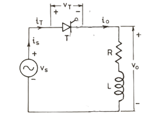
The circuit diagram of a single phase half wave controlled rectifier with RL load is shown above. This circuit
consists of a thyristor T, source Vs and RL load. The output voltage is the voltage across the load and shown
as Vo. Output current is the current through the load and shown as io.
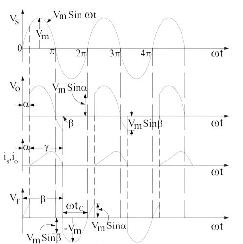
The waveform of source voltage, load voltage, load current and voltage across thyristor is shown above. It is assumed that the thyristor T is fired at an angle ωt = α. As soon as the thyristor T is fired at ωt = α, load voltage equal to the source voltage instantaneously appears across the load terminal. This is because, the thyristor is forward biased in between ωt = 0 to α. Hence, once the thyristor is gated, it starts conducting.
However, the current does not start at this instant of firing. This is just because of the nature of load. Since, the load is inductive, it will not allow any sudden change. Therefore, at ωt = α, the output current will be zero and will gradually increase. The output current will become maximum and then start decreasing. It should be noted here that, this behavior of load current io will not be observed for purely resistive load.
At ωt = π, the load voltage Vo reduces to zero. However, the load current will not be zero at this instant because of inductance L. Due to this, thyristor will not turn off, even though it is reversed biased. Rather it will continue to conduct till ωt = β. At ωt = β, the load current becomes zero and thyristor is reversed biased, hence it will turn off. This is a case of natural commutation.
After ωt = β, Vo = 0 and io = 0. At ωt = (2π+α), the SCR is triggered again, Vo is applied to the load and load current develops as discussed before. The angle β where the load current becomes zero is called extinction angle and the angle (β-α) for which thyristor is ON is called conduction angle.
Carefully observe the voltage across the thyristor. The SCR is reverse biased from ωt = β to ωt = 2π.
During this period, the current through thyristor is also zero. Therefore, circuit turn off time is tc = [(2π
– β) / ω] second. This time must be greater than the thyristor turn-off time otherwise thyristor may turn on at undesired instant and will lead to commutation failure.
The Voltage equation is :
$$V_{m}~ sin \omega t = Ri_0+L \frac {dI_0}{dt}$$
The load current io consist of two component, one steady state component is and the
transient component it. Here is is given by
$$i_{s} = \frac {V_m}{\sqrt{ (R^2+X^2)}}sin(\omega t- \phi)$$
The transient component it can be obtained from force free equation
$$Ri_t + L\frac{di_t}{dt} = 0$$
Its solution gives,
$$i_t = A e^{-\left(\frac{R}{L}\right)t}$$
$$i_o = i_s + i_t =\frac {V_m}{Z} sin(\omega t-\phi) + Ae^{-\left(\frac {R}{L}\right)t} .........(8)$$
Constant A can be obtained from the boundary condition at ωt = α. At time
$$t = \frac{\alpha}{\omega}$$
$$i_o = 0$$
Thus from equation (8)
$$A = -\frac {V_m}{Z} sin(\alpha - \phi )e^{\frac {R \alpha}{L \omega}}$$
Substitution of A in Eq. (8) gives
$$i_o = \frac {V_m}{Z} sin(\omega t- \phi) -\frac {V_m}{Z}sin(\alpha -\phi ) exp {-\frac{R}{\omega L}(\omega t-\alpha)}.......(9)$$
It is also seen from waveform of io in fig. 4 that when ωt = β, load current io = 0.
The average voltage Vo is given by
$$V_o = \frac {1}{2 \pi} \int_\alpha ^\beta V_m sin \omega t ~ d(\omega t) =\frac {V_m}{2 \pi}(cos \alpha -cos \beta).......(10)$$
The average load currrent Io is given by
$$I_o = \frac {V_m}{2 \pi R}(cos \alpha -cos \beta)$$
Rms Load voltage is
$$V_{or} = \left[ \frac {1}{2 \pi } \int_\alpha ^\beta V_m^2 ~ sin^2 ~ \omega t.d(\omega t)\right]^{\frac {1}{2}}$$
$$V_{or} = \frac {V_m}{2 \pi} \sqrt {\left[(\beta - \alpha)- \frac {1}{2}(sin 2 \beta - sin 2 \alpha )\right]}........(11)$$
3. Single Phase Half Wave Controlled Rectifier with RLE Load
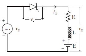
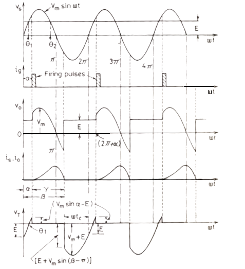
A Single Phase Half Wave Controlled Rectifier Circuit with RLE load is shown in Fig. 5. The counter emf E in
the load may be due to a battery or a DC motor. The minimum value of firing angle is obtained from the relation Vmsin ωt = E, this is shown to occur at an angle θ1 where
$$\theta_1 = sin^{-1}\left(\frac{E}{V_m}\right).......(12)$$
In case thyristor T is fired at an angle α <θ1, then E > Vs SCR is reversed biased
and therefore it will not turn on.
Similarly, maximum value of firing angle is θ2 = π - θ1 in Fig. 6. During
the interval load current io is zero, Load
voltage vo= E and during the time io is not zero, vo follows vs
curve, KVL gives the voltage differential equation as
$$V_m ~ sin \omega t = Ri_o + L\frac{di_o}{dt} + E.........(13)$$
The solution of this equation is made up of two components: namely steady-state current component is and the transient current component it. For conveninence, is may be thought of as the sum of is1 and is2, Where
is1 is the steady state current due to ac source voltage acting alone and is2 is that due to dc counter emf E acting alone due to source voltage Vmsin ωt is given by
$$i_{s1} = \frac{V_m}{Z} sin(\omega t-\phi)$$
If only E were present, then steady state current is2 would be given by
$$i_{s2} = -\left(\frac{E}{R}\right)$$
The transient current it is given by
$$i_t = Ae^{-\left(\frac{R}{L}\right)^t}$$
At ωt = α, io = 0, i.e., at t = α/ω, io = 0.
$$A = \left[\frac {E}{R}-\frac {V_m}{Z} sin(\alpha - \phi )\right]e^{-\frac{Ra}{L \omega}}$$
$$i_o =\frac {V_m}{Z}\left[sin(\omega t- \phi )-sin( \alpha - \phi)exp{-\frac {R}{\omega L}(\omega t- \alpha )}\right]-\frac {E}{R}\left[1-exp{-\frac{R}{ \omega L}(\omega t- \alpha)}\right].......(14)$$
Equation 11 is applicable for α ≤ ωt ≥ β. The extinction angle β depends upon load emf E, firing angle α and the load impedence angle φ the average load current io is given by
$$I_o = \frac{1}{2 \pi R} \bigg[V_m(cos \alpha -cos \beta )-E(\beta-\alpha) \bigg]..........(15)$$
Average load voltage Vo is given by
$$V_o= E+I_oR=E+ \frac {1}{2 \pi}\bigg[2V_m sin\left(\alpha + \frac{\gamma}{2}\right)sin\left(\frac {\gamma}{2}\right)-\gamma.E\bigg]$$
$$V_o=E\left(1-\frac {\gamma} {2 \pi}\right)+\frac {V_m} {\pi} sin\left(\alpha +\frac {\gamma}{2}\right)sin \left(\frac {\gamma}{2}\right)..........(16)$$
In case β is made equal to (γ+α) in the above expression, Equation (15) can be obtained.
If load inductance L is zero in Fig. 5, then extinction angle β = θ2 and γ = β - α
= θ2 - α but θ2 = π - θ1.
This gives β = θ2 = π - θ1 and γ = π - θ1 - α.
Putting this in Equation (15), we get average load current Io as under :
$$I_o = \frac {1}{ 2 \pi R} \bigg[V_m (cos \alpha +cos \theta_1)-E( \pi - \theta_1- \alpha)\bigg].......(17)$$
For no inductance in the load circuit, β = π - α. The RMS value of load current for L = 0 is obtained
as under:
$$I_{or} = \bigg[\frac {1}{2\pi R^2}\int_\alpha^{\pi-\alpha}(V_m sin \omega t-E)^2.d(\omega t)\bigg]^\frac {1}{2}.........(18)$$
Power delivered to load
$$P=I^2R+I_oE.......(19)$$
Supply power factor
$$= I_or^2R+I_o \frac {E}{V_sI_{or}}$$
Advantages of Half-wave controlled rectifier
- Half wave controlled rectifier is a simple circuit, We can easily construct.
- Low cost and Simple circuit with less number of components.
- Economical at initial state. Although there is a higher cost over time due to more power losses.
Disadvantages of Half-wave controlled rectifier
- The transformer utilization factor is low.
- They produce a low output voltage.
- DC saturation of transformer core resulting in magnetizing current and also some hysteresis losses and generation of harmonics.
- The power is delivered only during the one-half cycle of the input alternating voltage.
- Ripple factor is high, therefore required to give steady dc output.
Applications of Half-wave controlled rectifier
- AM radio
- Pulse generated circuits
- Single demodulation
- Voltage multiplier