
Single Phase Full Wave Silicon Controlled Rectifier with R Load, RL Load & RLE Load
Introduction
A controlled rectifier is an electronic circuit that converts alternating current (AC) into direct current
(DC). It consists of power electronic devices, typically thyristors or silicon-controlled rectifiers (SCRs),
which are controlled to switch the flow of current in a desired manner.
The main function of a controlled rectifier is to control the magnitude and polarity of the output DC voltage.
It is commonly used in various applications where precise control over the rectification process is required
such as power supplies, motor drives, battery chargers, and voltage regulators.
The controlled rectifier operates by using a triggering mechanism to turn on the thyristors at specific points
in the AC waveform. Once the thyristors are triggered, they conduct current until the AC voltage crosses zero
or until the thyristor is turned off. By controlling the timing of thyristor firing, the rectifier can vary
the average DC voltage output.
Single Phase Full Wave Controlled Bridge Rectifier
A single-phase controlled bridge rectifier converts alternating current (AC) input into a direct current (DC)
output using a bridge configuration of thyristors (SCRs). It provides full-wave rectification and allows for control over the output voltage. Here's how a single-phase controlled bridge rectifier works:
1. Bridge Configuration: The bridge rectifier consists of four thyristors connected in a bridge configuration,
along with a load resistor and a DC output terminal. The AC input voltage is connected across the two opposite
corners of the bridge, while the load resistor and the DC output terminal are connected across the other two
corners.
2. Triggering Control: The thyristors are triggered in a controlled manner using gate pulses to determine
their conduction timing. The thyristors are triggered in pairs, with one thyristor from each pair conducting
in alternate half-cycles of the input voltage.
3. Operation: During the positive half-cycle of the input voltage, the thyristors on the positive side of the
bridge (top two thyristors in the bridge configuration) are triggered to conduct. This allows the positive
half of the input voltage to appear across the load resistor and the DC output terminal.
4. Voltage Polarity Reversal: During the negative half-cycle of the input voltage, the thyristors on the
negative side of the bridge (bottom two thyristors in the bridge configuration) are triggered to conduct. This
allows the negative half of the input voltage to appear across the load resistor and the DC output terminal,
effectively reversing the polarity of the output voltage.
By controlling the timing of thyristor triggering, the average DC output voltage can be varied. The output of
a single-phase controlled bridge rectifier is a pulsating DC voltage with ripples. Additional filtering
components like capacitors or inductors can be employed to reduce the ripples and obtain a smoother DC
output.
Single-phase controlled bridge rectifiers are commonly used in various applications, including AC motor speed
control, uninterruptible power supplies (UPS), battery charging systems, and DC power supplies requiring
variable output voltage control.
It's important to note that practical implementations of single-phase controlled bridge rectifiers require
additional circuitry for triggering control, protection, and snubber circuits to ensure safe and efficient
operation.
1. Single Phase Full Wave Controlled Rectifier - R Load
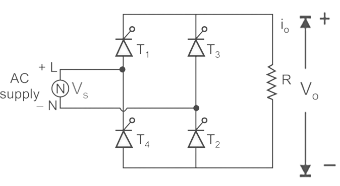
A fully controlled full-wave bridge rectifier is shown in Fig. 1. All the four devices used in the circuit are
thyristors T1-T4 for control of output power. In this circuit, diagonally opposite pair of thyristors are made
to conduct, and are commutated simultaneously. During the first positive half cycle, thyristors T1 and T2
are forward biased and if they are triggered simultaneously, the current flows through the load via thyristor
T1-load-T2-source. Thus, during positive half cycle, thyristors T1 and T2 are conducting. During the negative
half cycle of the ac input, thyristors T3 and T4 are forward biased and if they are triggered simultaneously,
the current flows through the load via thyristor T3-load-T4-source. Thyristors T1, T3 and T2, T4 are triggered
at the same firing angle α in each positive and negative half cycles of the supply voltage respectively. When
the supply voltage falls to zero, the current also becomes zero. Thus thyristors T1, T2 in positive half cycle
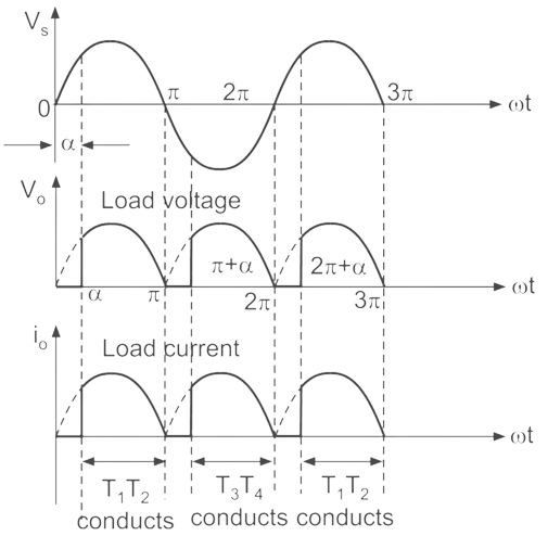
and T3 and T4 in negative half cycle turn off by natural commutation. The related voltage and current
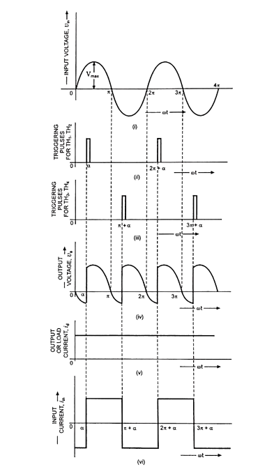
waveforms for this circuit are shown in Fig. 2.
The average of the waveform is determined by the following expression,
$$V_{o} = \frac {1}{\pi} \int_{\alpha}^{\pi} V_{m} \ sinwt \ d(wt) = \frac {V_{m}}{\pi} ( 1 + cos\alpha ) .......(1)$$
Average output current,
$$I_{o} = \frac {V_{o}}{R} = \frac {V_{m}}{\pi R} ( 1+ \cos\alpha) .......(2)$$
Power in the resistance,
$$P = I_{rms}^2*R.......(3)$$
Where,
$$I_{rms} = \frac {V_{m}}{R} \sqrt{\frac {1}{2} - \frac {\alpha}{2\pi} + \sin\left(\frac {2\alpha}{4\pi}\right)}.......(4)$$
$$V_{rms} = V_{m} \sqrt{\frac {1}{2} - \frac {\alpha}{2\pi} + \sin\left(\frac {2\alpha}{4\pi}\right)}.......(5)$$
2. Single Phase Full Wave Controlled Rectifier - RL Load
The current with RL load does not increase or decrease suddenly. So the waveform between the output current
and the output voltage is different. And the output current will tend to increase after each cycle. If the
inductance of the load is large enough, the output current is continuous.
When the SCR changes from the conductive state to the off state, the load will generate energy to maintain
that SCR continue to conduct. Therefore, after the polarity of the voltage is reversed and there is no control
pulse, then the output voltage Vo < 0.
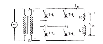
At firing angle α = 60°, thyristors TH1 and TH3 are triggered. Supply voltage from this instant appears across
the output terminals and forces the current through the load. The load current Idc is assumed to be constant.
This current also flows through the supply and the direction is from line to neutral, which is taken positive
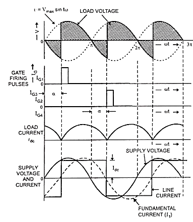
as shown in Fig. 4 along with the applied voltage. At instant π, the supply voltage reverses but because of
very large inductance L, the current keeps flowing in the same direction at constant magnitude Idc. Thus the
thyristors TH1 and TH3 remain in conducting state and therefore, the negative supply voltage appears across
the output terminals. At an angle π + α, thyristors TH2 and TH4 are triggered. With this, negative supply
voltage reverse biases thyristor TH1 through thyristor TH2 and thyristor TH3 through thyristor TH4 of
commutating thyristor TH1 and TH3. The current continues flowing in every half cycle and output voltage is
obtained as depicted in the figure. As illustrated the current is positive when TH1 and TH3 are conducting and
negative when TH2 and TH4 are conducting.
Current function,
$$i_{o~(wt)} = \frac {V_m}{Z}\left[ sin(wt-θ)- sin(\alpha-θ)e^{ \frac {-(wt-\alpha)}{wτ}}\right].......(6)$$
Solving for $\alpha$,
$$\alpha ≤ θ$$
$$θ = \tan^{-1}\left(\frac {wL}{R}\right) .......(7)$$
$$\alpha ≤ \tan^{-1}\left(\frac {wL}{R}\right) .......(8)$$
The dc (average value) is,
$$V_{o} = \frac {1}{\pi} \int_{\alpha}^{\alpha + \pi} V_{m} \sin{wt} ~ d(wt) = \frac {2V_{m}}{\pi} \cos {\alpha} .......(9)$$
$$I_{o} = \frac {1}{\pi R} \int_{\alpha}^{\alpha + \pi} V_{m} \sin{wt} ~ d(wt) = \frac {2V_{m}}{\pi R} \cos {\alpha} .......(10)$$
The amplitude of ac terms are calculated from,
$$V_{n} = \sqrt {a_{n}^2 + b_{n}^2} .......(11)$$
$$a_{n} = \frac {2V_{m}}{\pi}\left[\frac {cos(n+1)\alpha}{n+1} - \frac {cos(n-1)\alpha}{n-1}\right].......(12)$$
$$b_{n} = \frac {2V_{m}}{\pi}\left[\frac {sin(n+1)\alpha}{n+1} - \frac {sin(n-1)\alpha}{n-1}\right].......(13)$$
$$I_{rms} = \sqrt {I_o^2+ ∑_{n=2,4,6…}^{∞} \left(\frac {I_{n}^2}{\sqrt 2}\right)^2 } .......(14)$$
3. Single Phase Full Wave Controlled Rectifier - RLE Load
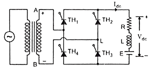
The circuit arrangement of a Single Phase Full Wave Controlled Rectifier with RLE load is shown in Fig. 5.
During positive half cycle, thyristors TH1 and TH3 are forward biased and start conducting at ωt = α. The load
current flows through TH1, motor and TH3. At ωt = π, the supply voltages reverses. Because of inductance L
thyristors TH1 and TH3 continue to conduct beyond ωt = π. From ωt = π to ωt = 2π, thyristors TH3 and TH4 are
forward biased. When TH2 and TH4 are triggered at ωt = π + α, thyristors TH1 and TH3 are subjected to reverse
bias and are turned off by natural commutation. Load current is transferred from TH1 and TH3 to TH2 and TH4.
This mode of operation continues till TH1 and TH3 are triggered in the next positive half cycle. Load Current
tend to almost constant due to high L/R ratio.
When we use a load with components R, L, E, the output waveform of the circuit is drawn as shown in the above Fig. 6. If the SCR is conducting, the output waveform is the same that of the RL load rectifier circuit.
When no SCR is conducting (Io = 0) the output voltage is equal to E (Vo = Vdc).
For conduction,
$$\alpha ≥ \sin^{-1}\left(\frac {V_{dc}}{V_{m}}\right) .......(15)$$
The average bridge output voltage is,
$$V_{o} = \frac {2V_m}{\pi} \ cos\alpha.......(16)$$
The average load current is,
$$I_{o} = \frac {2V_{m} \ cos\alpha}{\pi R} - \frac {V_{dc}}{R} .......(17)$$
The expression for the $V_{rms}$ and $I_{rms}$ are,
$$V_{rms} = V_{max} \sqrt{\frac {\pi-\alpha}{2\pi} + \frac {\sin 2\alpha}{4\pi}}.......(18)$$
$$I_{rms} = \frac {V_{max}}{R} \sqrt{\frac {\pi-\alpha}{2\pi} + \frac {\sin 2\alpha}{4\pi}}.......(19)$$
Power absorbed by dc voltage is,
$$P_{dc} = I_{o} * V_{dc } .......(20)$$
Advantages of Single Phase Full Wave SCR
The single-phase controlled full-wave rectifier offers relatively high efficiency in converting AC to DC power. This is because it utilizes both halves of the input AC waveform, ensuring better utilization of power.
Compared to half-wave rectifiers, the full-wave rectifier provides a smoother output waveform. It reduces the ripple content in the DC output, resulting in a more stable and constant DC voltage.
The full-wave rectifier configuration can provide a higher average DC output voltage compared to a half-wave rectifier. This is due to the utilization of both positive and negative halves of the input AC waveform.
By using controlled switching devices like thyristors, the rectification process can be controlled, allowing for adjustable output voltage and power control. This feature is particularly useful in applications that require variable voltage or power levels.
Disadvantages of Single Phase Full Wave SCR
The single-phase controlled full-wave rectifier is more complex compared to a half-wave rectifier. It requires additional components like thyristors, triggering circuits, and gate control circuits. This complexity increases the cost and can make the circuit more susceptible to faults.
The use of controlled switching devices can introduce harmonic distortion in the output waveform. These harmonic components can cause interference in other electrical equipment connected to the same power supply, leading to performance issues or malfunctions.
The additional components required for control and switching increase the overall cost of the rectifier circuit. The cost of thyristors and their associated control circuits can be significant compared to simple diodes used in half-wave rectifiers.
The introduction of thyristors or other controlled switching devices adds complexity and potential points of failure in the circuit. This can reduce the overall reliability of the rectifier compared to simpler rectifier configurations.
Applications of Single Phase Full Wave SCR
Single-phase full-wave controlled rectifiers are commonly used in power supplies for electronic devices and equipment. They convert AC voltage from the mains power supply to a regulated DC voltage suitable for powering electronic circuits.
Single-phase full-wave controlled rectifiers are used in motor drive systems to convert AC power into DC power to drive DC motors. By controlling the firing angle of the rectifier, the speed and torque of the motor can be regulated.
Single-phase full-wave controlled rectifiers are employed in battery charging systems to convert AC power to DC power for charging batteries. The firing angle control allows for regulating the charging current and voltage to prevent overcharging and optimize the charging process.
Electroplating processes often require a controlled DC power supply. Single-phase full-wave controlled rectifiers can be used to provide the required DC voltage and current for electroplating applications.
Single-phase full-wave controlled rectifiers are utilized in welding machines to convert AC power to DC power for welding operations. They provide a stable and controlled DC current necessary for welding applications.
In some UPS systems, single-phase full-wave controlled rectifiers are used to rectify the incoming AC power and charge the backup batteries. This ensures a continuous supply of power in the event of a power outage.
Single-phase full-wave controlled rectifiers, in conjunction with additional power electronic devices such as thyristors or transistors, are employed in variable speed drives to control the speed of AC motors. The rectifier section converts AC power to DC power, which is further processed to generate variable-frequency AC power to drive the motor at different speeds.