
Single Phase Full Wave Mid-point Converter with R Load and RL Load
Introduction
A full-wave controlled mid-point converter is a power electronics circuit that is used to convert alternating current (AC) input voltage to a desired output voltage level. It is called a mid-point converter because it operates with a mid-point voltage, which is typically half of the input voltage.
The full-wave controlled mid-point converter consists of a bridge rectifier, a center-tapped transformer and two thyristors (SCRs). The bridge rectifier is connected to the AC input voltage source, and its output is connected to the center-tapped transformer. The center tap of the transformer is connected to the ground or reference potential.
The operation of the full-wave controlled mid-point converter can be divided into two modes: positive half-cycle mode and negative half-cycle mode.
During the positive half-cycle mode:
- The thyristor connected to the positive terminal of the bridge rectifier is triggered and conducts current. This allows the positive half-cycle of the AC voltage to flow through the transformer.
- The mid-point voltage, which is half of the input voltage, is developed across the center tap of the transformer and is available for use.
During the negative half-cycle mode:
- The thyristor connected to the negative terminal of the bridge rectifier is triggered and conducts current. This allows the negative half-cycle of the AC voltage to flow through the transformer.
- The same mid-point voltage is developed across the center tap of the transformer and is available for use.
By controlling the triggering angles of the thyristors, the output voltage of the full-wave controlled mid-point converter can be varied. By delaying or advancing the triggering of the thyristors, the conduction angle of the AC voltage can be controlled, thereby controlling the average output voltage. This control enables regulation of the output voltage despite variations in the input voltage.
1. Single Phase Full Wave Mid-point Converter - R Load
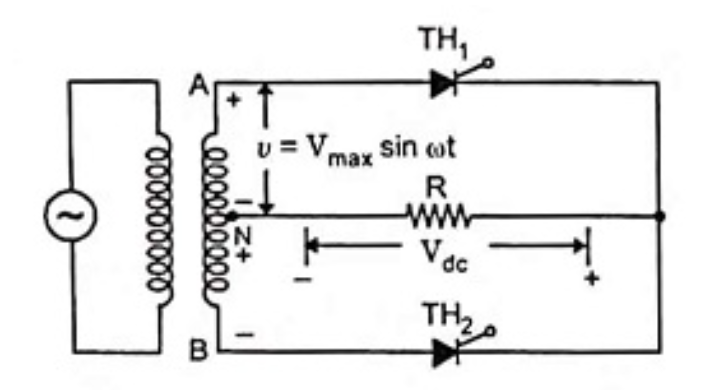
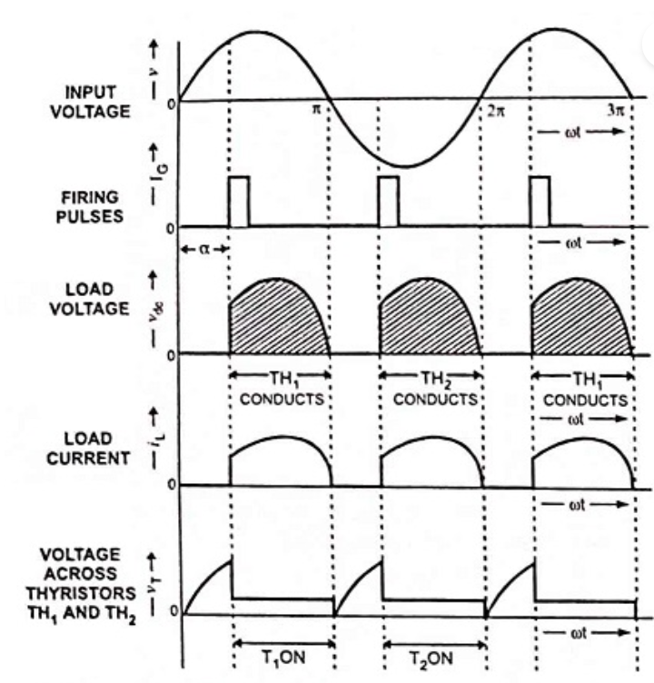
When terminal A shown in the circuit is positive w.r.t. midpoint N of the transformer secondary, point B will have negative polarity w.r.t. mid-point. Under this condition the thyristor TH1 conducts when it is fired at an angle α. The waveforms of the load voltage and load current are shown in Fig. 2. The current continues to flow up to angle π radians or 180° when the supply voltage reverses its polarity and thyristor TH1 gets turned off by natural commutation. During the negative half cycle of ac supply, the terminal B of the transformer secondary is positive w.r.t. to mid-point N. Thyristor TH2 gets turned on when it is gated. Usually the firing angles for the two thyristors are taken to be equal so as to avoid unequal distribution of load current in the two halves of input cycle. Each half of the input wave is applied across the load. Thus, across the load, there are two pulses of current in the same direction. Hence the ripple frequency across the load is twice that of the input supply frequency. It is clear from Fig. 2 that with pure resistive load, the load current is always discontinuous.
The output dc voltage across the resistive load is given by
$$V_{dc} = \frac {1}{\pi} \int_{\alpha}^{\pi} V_{max}\ sinwt \ dwt$$
$$V_{dc} = \frac {V_{max}}{\pi}(1+cos\alpha)..........(1)$$
The average load current is given by
$$I_{dc} = \frac {V_{dc}}{R} = \frac {V_{max}}{\pi R}(1+cos\alpha)..........(2)$$
The rms of output voltage is
$$V_{o~(rms)} = \left[ \frac {1}{\pi} \int_{0}^{\pi} V_{max}^2 ~ sin^2wt ~ dwt \right]^{1/2}$$
$$V_{o~(rms)} = V_{max} \left[ \frac {\pi-\alpha}{2\pi} + \frac {sin2\alpha}{4\pi} \right]^{1/2}..........(3)$$
The rms of output current is
$$I_{o ~ rms} = \frac {V_{o ~ rms}}{R} = \frac {V_{max}}{R} \bigg[\frac {\pi-\alpha}{2\pi} + \frac {sin2\alpha}{4\pi} \bigg]^{1/2}..........(4)$$
2. Single Phase Full Wave Mid-point Converter - RL Load
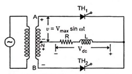
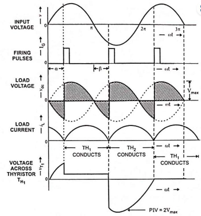
In positive half cycle thyristor TH1 conducts when it is fired at an angle α. When ωt = π the cycle reverses and the voltage at terminal A goes negative while at terminal B it goes positive. At this value of angle thyristor TH1 still conducts due to current circulated as a result of decay of energy stored in the inductor. The rate of decay is determined by L/R ratio. When the energy stored in the inductor falls to zero, thyristor TH1 is turned off and the load current falls to zero value at an angle called extinction angle β. The extinction angle β may be greater than, equal to, or less than the firing angle α depending upon whether the value of inductance is more than, equal to or less than the critical value respectively.
$$V_{dc} = \int_{\alpha}^{\pi+\alpha} V_{max} ~ sinwt ~ dwt$$
$$V_{dc} = \frac {2V_{max}}{\pi}cos\alpha..........(5)$$
Some conclusions may be made from above equation:
- Output voltage will have the highest value for α = 0.
- Output voltage will be zero for α = 90°. It means that the output voltage will contain equal positive and negative areas, giving zero output voltage.
- For firing angle α exceeding 90°, the converter operates in inversion mode. The voltage will be negative maximum for α = 180°.
Advantages of Single Phase Full Wave Mid-point Converter
The full wave controlled mid-point converter allows power to flow in both directions, enabling bidirectional energy transfer. This feature is especially useful in applications where power needs to be converted between AC and DC, or where energy needs to be stored and retrieved, such as in energy storage systems or electric vehicle charging.
By using a full wave configuration, the mid-point converter can achieve lower input and output current ripple compared to half-wave converters. This results in improved power quality, reduced electromagnetic interference (EMI), and lower stress on connected components.
The full wave controlled mid-point converter has a higher efficiency compared to other converter topologies. This is because it utilizes both the positive and negative halves of the input waveform, maximizing the power conversion efficiency.
The full wave controlled mid-point converter reduces harmonic distortion in the output waveform. This is beneficial for applications that require a clean and sinusoidal output voltage, such as grid-connected systems or sensitive loads.
The mid-point converter provides better voltage regulation capabilities due to its ability to control the output voltage by adjusting the phase angle and duty cycle of the switching devices. This allows for precise control over the output voltage, making it suitable for applications that require tight voltage regulation, such as power supplies or motor drives.
The full wave controlled mid-point converter can achieve higher power density and compact size compared to other converter topologies. This is advantageous in applications where space is limited or weight reduction is important, such as in portable devices or electric vehicles.
The full wave controlled mid-point converter can be easily interfaced with various control strategies and modulation techniques. It can also accommodate different types of loads, making it a versatile choice for a wide range of applications.
Disadvantages of Single Phase Full Wave Mid-point Converter
Compared to simpler converters like half-wave rectifiers, full wave controlled mid-point converters are more complex in terms of circuitry and control algorithms. This complexity can lead to increased costs, design challenges, and potential points of failure.
The operation of a full wave controlled mid-point converter involves switching actions that can introduce higher levels of harmonic distortion into the output waveform. This can lead to increased losses, reduced power quality, and potential interference with other sensitive equipment connected to the system.
The full wave controlled mid-point converter requires the use of semiconductor devices (such as thyristors or transistors) for switching actions. These devices have finite switching times and can experience switching losses, resulting in reduced efficiency compared to simpler rectifier topologies.
The full wave controlled mid-point converter operates with a floating mid-point voltage, which requires careful balancing to ensure that the two output voltages are equal. Any imbalance in the mid-point voltage can lead to uneven voltage sharing between the two output phases, potentially causing issues in connected loads or requiring additional control measures.
The full wave controlled mid-point converter is generally suitable for applications where the output voltage is lower than the input voltage. It becomes less efficient and more complex to implement when higher output voltages are required.
The control strategy for the full wave controlled mid-point converter can be more challenging compared to simpler converters. The control algorithm needs to manage the switching of multiple semiconductor devices and ensure proper synchronization and voltage balancing, which can increase the complexity of the control system.
Applications of Single Phase Full Wave Mid-point Converter
Renewable Energy Systems
Energy Storage Systems
Microgrids and Islanded Systems
Battery Charging Systems
Variable Frequency Drives