
To study the resonance condition of a series LCR circuit
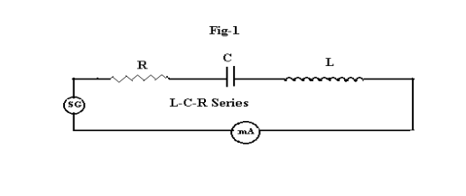
(Series L-C-R) When the resistor R, inductor L and capacitor C are connected in series with a source of emf E , the circuit is called as the series resonant or series tuned circuit ( figure-1). This is an acceptor circuit, that means it allows maximum current to flow through it at a particular ( resonant ) frequency and at all other frequencies it allows less current.
In A.C. circuits the voltage and the current are usually out of phase. Across the inductor, the current lags behind the voltage by 900 , where as across the capacitor, the current leads the voltage by 900 . But across the resistor the voltage and current both are in phase. Under certain conditions, the voltage and current are in phase, even though the circuit consists of L , C and R and the circuit behaves as a pure resistor. This phenomenon is called resonance. This occurs at a single frequency known as resonant frequency. At this frequency the capacitive reactance( Xc = 1/ωC) and the inductive reactance( XL = ωL) are equal and opposite in direction. So they get cancelled each other and only resistance acts.
The impedance of the circuit is given by
Z = R + j (ωL- 1/ωC )
At resonance the reactive term disappears
ωL - 1/ωC = 0
The impedance is minimum i.e.
Z = R
The current is maximum
So
ωL = 1/ωC

At this frequency the current is maximum and this frequency f0 is called resonant frequency. The circuit has selective properties. To compare selectivity or sharpness of resonance, a band of frequencies is chosen at which the current falls to 2 1 times ( half power points ) of its maximum value. The frequency difference (f2 – f1 ) between the half power points is called the bandwidth.