
Design of XOR, XNOR Gates using SPICE Code
Spice Code Platform
Code -
- The code block that defines the name of the gate, includes file, and declares parameters should be placed first, followed by the code block that defines the voltage source, then the block that defines the inverter subcircuit, followed by the netlist statement that instantiates and calls the respective gate subcircuit, then the block that defines the input waveform 'a', 'b' followed by the control statements to run the circuit and plot the required graphs, and then finally the end of code block.
- Drag and drop the code blocks to arrange them in the order mentioned above.
- Now enter the name of the MOSFET model file to be included ("PTM_45nm.txt").
- To define the voltage source, enter a name for it and then select vdd as the positive terminal and 0 or gnd as the negative terminal. Now, define the subcircuit by giving it a name and also giving names to the input and output arguments of the subcircuit. Inside this subcircuit, we need to call inverter and pass transistor subcircuits which are built using PMOS and NMOS, and these connections are given as follows:
The connections for each MOSFET should follow this template:
          INSTANCE_NAME DRAIN GATE SOURCE BODY
          NAME_OF_MOSFET_AS_MENTIONED_IN_MODEL_FILE_INCLUDED w=WIDTH l=LENGTH
Wiring Steps:
- Assign a unique instance name to each NMOS and PMOS transistor.
- Connect the body of PMOS to VDD, and the body of NMOS to GND or 0.
- Make the remaining connections as shown in previous experiments and circuit diagrams.
Then inside the main subcircuit block, instantiate the inverter and pass transistor subcircuits according to the following connections in the figures.
Now end the subcircuit block by .ends.
Now call this gate subcircuit by giving an instance name, then by giving 'a', 'b' as inputs and 'out' as output and then complete the call by typing in the respective gate subcircuit name.
Note: While giving names to the subcircuit, nodes, variables and instance names, make sure that they begin with either alphabets, '%', '$' or '_' character only and they can only contain alphanumeric characters, '%', '$' and '_' characters only. The SPICE code is case insensitive so make sure to not give the same names to any two variables in the same circuit or subcircuit irrespective of the case.
Schematic Diagrams
Below are the schematic diagrams for the XOR and XNOR gate circuits. The diagrams show the connections for the bulk terminals of both PMOS and NMOS transistors, as well as the sizes (W/L ratios) of the transistors:
XOR Gate:
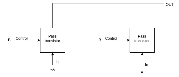
XNOR Gate:
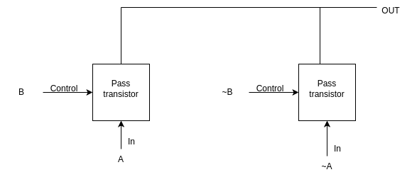
- PMOS: Connect bulk to VDD
- NMOS: Connect bulk to GND or 0
Note: Always ensure the bulk terminals are properly connected: PMOS bulk to VDD, NMOS bulk to GND or 0.
Steps to Perform the Simulation
The simulation page uses colored code blocks to help you visually identify each step in building the SPICE code for XOR/XNOR gates. Each block represents a key part of the code and is color-coded for clarity. Follow the instructions below for a smooth experience:
- Arrange the Colored Code Blocks:
- Start with the blue block for the MOSFET model file (
PTM_45nm.txt) and parameter declarations. - Next, use the green block to define the voltage source (
vddas positive,gndor0as negative). - The yellow block is for the inverter and pass transistor subcircuit definitions, including input/output names and PMOS/NMOS connections. Use the format:
INSTANCE_NAME DRAIN GATE SOURCE BODY MODEL_FILE w=WIDTH l=LENGTH - The red block is for building the XOR/XNOR gate subcircuit using the above subcircuits.
- The teal block is for instantiating the gate subcircuit in your main code.
- The purple block is for declaring the input waveforms.
- The purple block is also for control statements to run and plot the simulation.
- The gray block marks the end of your SPICE code.
- Complete Each Block:
- Fill in the blanks in each colored block with the required values and names.
- Arrange the blocks in the order listed above for a valid simulation.
- Naming Conventions:
- Start names with an alphabet,
%,$, or_. - Names can include alphanumeric characters,
%,$, and_. - SPICE code is case-insensitive; do not use duplicate names (even with different cases).
Step-by-Step Wiring Tables
XOR Gate:
| Step | Action | Description |
|---|---|---|
| 1 | Build Inverter | Construct inverter subcircuit for input signals |
| 2 | Add Pass Transistors | Place NMOS and PMOS pass transistors for each input branch |
| 3 | Connect Control Signals | Use complementary inputs to control transmission gates |
| 4 | Combine Outputs | Merge outputs from transmission gates to form XOR output |
XNOR Gate:
| Step | Action | Description |
|---|---|---|
| 1 | Build Inverter | Construct inverter subcircuit for input signals |
| 2 | Add Pass Transistors | Place NMOS and PMOS pass transistors for each input branch |
| 3 | Connect Control Signals | Use complementary inputs to control transmission gates |
| 4 | Combine Outputs | Merge outputs from transmission gates to form XNOR output |
Observations
- After completing and arranging the colored blocks, click "Validate." If everything is correct, you will see a "Success" message, a report, and input/output graphs in the Observations section.
- Use the "Expand Waveform" button to view larger graphs for better analysis.
- Observe how the input signals and output waveforms relate to the XOR/XNOR gate operation.
Summary:
This improved procedure matches the simulation interface, making it easier for beginners to follow each step and understand the role of every code block. The color coding and clear instructions help ensure a successful SPICE simulation for XOR/XNOR gates.