Detection of SA0 faults on a VLSI circuit for 4x16 decoder constructed with two 3x8 decoders
PROCEDURE
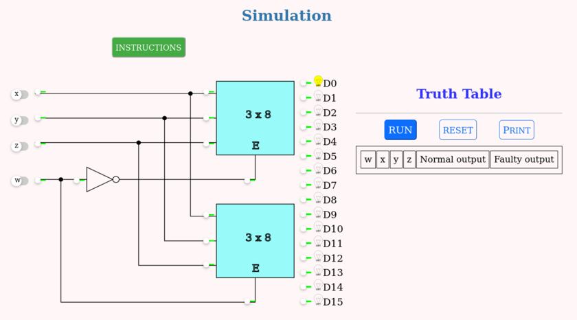
- The circuit simulated is as shown in the below image.
- Click the input switches to select the required inputs named "x", "y", "z" and "w". Switch in the "ON" state is
 and "OFF" state is
  .
. - The simulation will display corresponding output. Output is displayed as a glowing bulb.
- Press the "RUN" button to display the output in the truth table. Verify the input values and corresponding output values from the truth table.
- "RESET" button clears all entries of truth table and resets the simulator.
- At specific positions, small switches make the lines stuck-at-0. Clicking them simulates SA0 faults at the said locations. Line is stuck-at-0 if
 . The line is normal if switch is green
  .
. - Repeat above steps for all possible inputs and verify the truth table.
The simulation should be displayed as shown: