
Rolling processes
Theory
It is the process of plastically deforming metal by passing it between rolls. Rolling may be defined as the reduction of the cross-sectional area of the metal stock, or the general shaping of the metal products, through the use of the rotating rolls. It allows a high degree of closed-loop automation and very high speeds, and is thus capable of providing high-quality, close tolerance starting material for various secondary sheet metal working processes at a low cost.
- Rolling is the most widely used forming process, which provides high production and close control of final product.
- The metal is subjected to high compressive stresses as a result of the friction between the rolls and the Rolling process metal surface.
Introduction - Hot and Cold Rolling Processes
Hot Rolling
The initial breakdown of ingots into blooms and billets is generally done by hot-rolling. This is followed by further hot rolling into plate, sheet, rod, bar, pipe, rail. The distinctive mark of hot rolling is not a crystallized structure, but the simultaneous occurrence of dislocation propagation and softening processes, with or without re-crystallization during rolling.
Hot rolling offers several advantages:
a) Flow stresses are low, hence forces and power requirements are relatively low, and even very large work pieces can be deformed with equipment of reasonable size.
b) Ductility is high; hence large deformations can be taken (in excess of 99% reduction).
c) Complex part shapes can be generated.
Cold Rolling
The cold-rolling of metals has played a major role in industry by providing sheet, strip, foil with good surface finishes and increased mechanical strength with close control of product dimensions. Cold rolling, in the everyday sense, means rolling at room temperature, although the work of deformation can raise temperatures to 100-200°C. Cold rolling usually follows hot rolling.
Cold rolling has several advantages:
a) In the absence of cooling and oxidation, tighter tolerances and better surface finish can be obtained.
b) Thinner walls are possible.
c) The final properties of the workpiece can be closely controlled and, if desired, the high strength obtained during cold rolling can be retained or, if high ductility is needed, grain size can be controlled before annealing.
d) Lubrication is, in general, easier.
TYPICAL ARRANGEMENT OF ROLLERS FOR ROLLING MILLS
TWO-HIGH MILL, PULLOVER
The stock is returned to the entrance for further reduction.
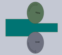
Figure 2: Two-high mill, Pullover
TWO-HIGH MILL, REVERSING
The work can be passed back and forth through the rolls by reversing their direction of rotation.
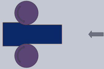
Figure 3: Two-high mill, reversing
THREE-HIGH MILL
Consist of upper and lower driven rolls and a middle roll, which rotates by friction.

Figure 3: Three-high mill
FOUR-HIGH MILL
Small-diameter rolls (less strength & rigidity) are supported by larger-diameter backup rolls.

Figure 4: Four-high mill
CLUSTER MILL OR SENDZIMIR MILL
Each of the work rolls is supported by two backing rolls.
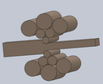
Figure 5: Cluster mill or sendzimir mill
CONTINUOUS ROLLING
- Use a series of rolling mill and each set is called a stand.
- The strip will be moving at different velocities at each stage in the mill.
- The un coiler and windup reel not only feed the stock into the rolls and coiling up.
- the final product but also provide back tension and front tension to the strip.
- The speed of each set of rolls is synchronised so that the input speed of each stand is equal to the output speed of preceding stand.
Given below is the example of a four stand continuous mill or tandem mill. Typical arrangement of rollers for rolling mills.
Planetary Mill
Consist of a pair of heavy backing rolls surrounded by a large number of planetary rolls.
- Each planetary roll gives an almost constant reduction to the slab as it sweeps out a circular path between the backing rolls and the slab.
- As each pair of planetary rolls ceases to have contact with the work piece, another pair of rolls makes contact and repeat that reduction.
- The overall reduction is the summation of a series of small reductions by each pair of rolls.
- Therefore, the planetary mill can hot reduces a slab directly to strip in one pass through the mill.
- The operation requires feed rolls to introduce the slab into the mill, and a pair of planishing rolls on the exit to improve the surface finish.

Figure 6: Typical arrangement of rollers for rolling mill
ROLLING MILLS
Rolling mill is a machine or a factory for shaping metal by passing it through rollers Successive stands of a large continuous mill.
A rolling mill basically consists of:
- rolls
- bearings
- a housing for containing these parts
- a drive (motor) for applying power to the rolls and controlling the speed
- Requires very rigid construction, large motors to supply enough power (MN).
CONVENTIONAL HOT OR COLD-ROLLING
The objective is to decrease the thickness of the metal with an increase in length and with little increase in width.
- The material in the centre of the sheet is constrained in the z direction (across the width of the sheet) and the constraints of undeformed shoulders of material on each side of the rolls prevent extension of the sheet in the width direction.
- This condition is known as plane strain. The material therefore gets longer and not wider.
TRANSVERSE ROLLING
- Using circular wedge rolls.
- Heated bar is cropped to length and fed in transversely between rolls.
- Rolls are revolved in one direction.
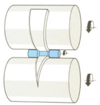 >
>Figure 7: Transverse rolling
SHAPED ROLLING OR SECTION ROLLING
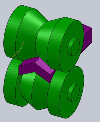
Figure 8: Shaped rolling
- A special type of cold rolling in which flat slab is progressively bent into complex shapes by passing it through a series of driven rolls.
- No appreciable change in the thickness of the metal during this process.
- Suitable for producing moulded sections such as irregular shaped channels and trim. A variety of sections can be produced by roll forming process using a series of forming rollers in a continuous method to roll the metal sheet to a specific shape.
Fundamental Concept of Metal Rolling
ASSUMPTIONS
- The arc of contact between the rolls and the metal is a part of a circle.
- The coefficient of friction, μ, is constant in the theory, but in reality μ varies along the arc of contact.
- The metal is considered to deform plastically during rolling.
- The volume of metal is constant before and after the rolling. In practical the volume might decrease a little bit due to close-up of pores.
- The velocity of the rolls is assumed to be constant.
- The metal only extends in the rolling direction and no extension in the width of the material.
- The cross sectional area normal to the rolling direction is not distorted.
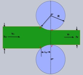
FORCES AND GEOMETRICAL RELATIONSHIPS IN ROLLING
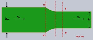
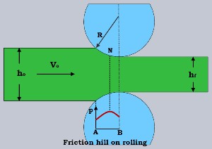
- A metal sheet with a thickness h₀ enters the rolls at the entrance plane xx with a velocity vₒ.
- It passes through the roll gap and leaves the exit plane yy with a reduced thickness h_f and at a velocity v_r.
- Given that there is no increase in width, the vertical compression of the metal is translated into an elongation in the rolling direction.
- Since there is no change in metal volume at a given point per unit time throughout the process, therefore
bh₀ν₀ = bhν = h_fν_f ... Eq.1
where:
- b is the width of the sheet
- v is the velocity at any thickness h intermediate between h₀ and h_f
From Eq.1:
bh₀v₀ = bhv = bh_fv_f
given that, b₀ = b_f
then we have: v₀h₀ = v_fh_f
v₀/v_f = h_f/h₀ ... Eq.2
The velocity of the sheet must steadily increase from entrance to exit such that a vertical element in the sheet remain undistorted.
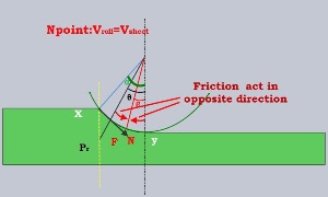
Forces Acting on the Metal
At only one point along the surface of the contact between the roll and the sheet, the two forces act on the metal:
- a radial force P_r
- a tangential frictional force F
If the surface velocity of the roll v_r equal to the velocity of the sheet, this point is called neutral point or no-slip point. For example, point N.
Between the entrance plane(xx) and the neutral point the sheet is moving slower than the roll surface, and the tangential frictional force, F, act in the direction (see fig.) to draw the metal into the roll.
On the exit side(yy) of the neutral point, the sheet moves faster than the roll surface. The direction of the frictional force is then reversed and oppose the delivery of the sheet from the rolls.
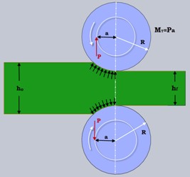
Specific Roll Pressure
P_r is the radial force, with a vertical component P (rolling load - the load with which the rolls press against the metal).
The specific roll pressure, p, is the rolling load divided by the contact area.
p = P / (bl_p) ... Eq.3
where b is the width of the sheet.
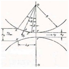
L_p is the projected length of the arc of the contact
L_p ≈ √(RΔh) ... Eq.4
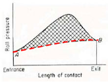
Pressure Distribution
- The distribution of the roll pressure along the arc of contact shows that the pressure rises to a maximum at the neutral point and then falls off.
- The pressure distribution does not come to a sharp peak at the neutral point, which indicate that the neutral point is not really a line on the roll surface but an area.
- The area under the curve is proportional to the rolling load.
- The area in shade represent the force required to overcome frictional forces between the roll and the sheet.
- The area under the dashed line AB represents the force required to deform the metal in plane homogeneous compression.
ROLL BITE CONDITION
For the work piece to enter the throat of the roll, the component of the friction force must be equal to or greater than the horizontal component of the normal force.
F cos α ≥ P_r sin α
F/P_r ≥ sin α / cos α ≥ tan α
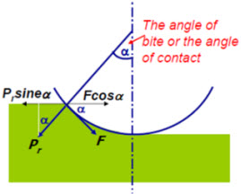
But we know that:
F = μP_r
μ = tan α ... Eq.5
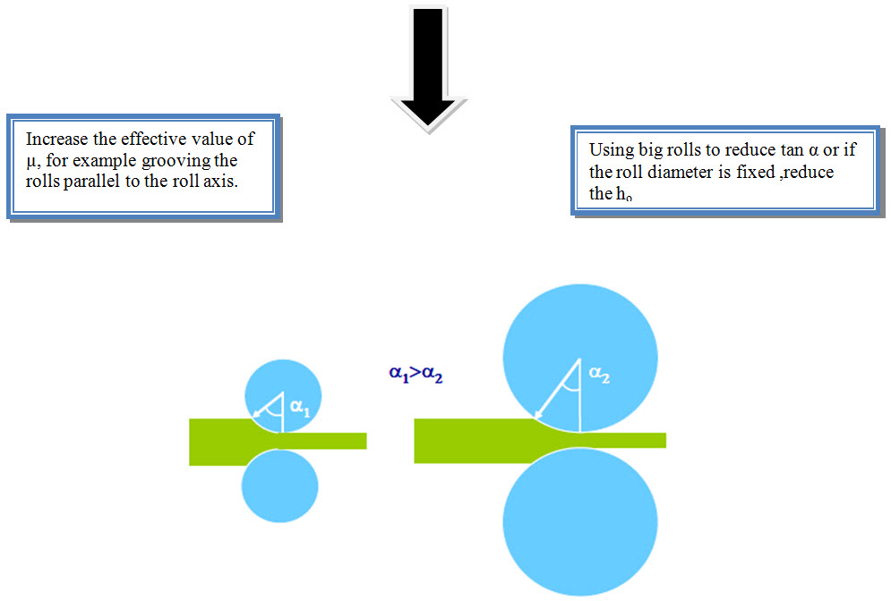
Conditions for Rolling
- If tan α > μ, the work piece cannot be drawn.
- If μ = 0, rolling cannot occur.
- Therefore Free engagement will occur when μ > tan α
THE MAXIMUM REDUCTION
From triangle ABC, we have:
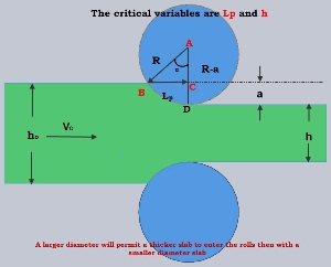
R² = L_p² + (R - a)²
L_p² = R² - (R² - 2Ra + a²)
L_p² = 2Ra - a²
As a is much smaller than R, we can then ignore a²
Torque and Power
Torque is the measure of the force applied to a member to produce rotational motion.
Power is applied to a rolling mill by applying a torque to the rolls and by means of strip tension.
Power Distribution
The power is spent principally in four ways:
a) The energy needed to deform the metal.
b) The energy needed to overcome the frictional force.
c) The power lost in the pinions and power-transmission system.
d) Electrical losses in the various motors and generators.
Remarks: Losses in the windup reel and uncoiler must also be considered.
Moment Arm Ratio
The total rolling load is distributed over the arc of contact in the typical friction-hill pressure distribution. However the total rolling load can be assumed to be concentrated at a point along the arc of the contact at a distance a from the line of centres of the rolls. The ratio of the moment arm a to the projected length of the arc of the contact L_p can be given as:
λ = a / L_p = a / √(RΔh)
where λ is 0.5 for hot-rolling and 0.45 for cold rolling.
>
Torque Calculation
The torque M_T is equal to the total rolling load P multiplied by the effective moment arm a. Since there are two rolls, the torque is given by:
M_T = 2Pa
Power Calculation
During one revolution of the top roll the resultant rolling load P moves along the circumference of a circle equal to 2πa. Since there are two work rolls, the work done W is equal to:
Work = 2(2πa)P
Since the power is defined as the rate of doing work, i.e., 1W = 1Js⁻¹, the power (in watts) needed to operated a pair of rolls revolving at N Hz (s⁻¹) in deforming metal as it flows through the roll gap is given by:
W = 4πaPN
where P is in Newton and a is in meters
- Forces and geometrical relationships in rolling
- Roll bite conditions and maximum reduction
- Torque and power calculations
Each section includes relevant diagrams and mathematical equations to provide a comprehensive understanding of the rolling process.