R-L-C Circuit Analysis 
Theory
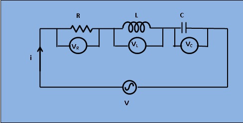
With reference to figure 1, the application of Kirchoff's law results, $$V=I R + jIX_L + \frac{I}{j\omega C}$$ , Where, $$V_R = IR, V_L=jIX_L, V_C=\frac{I}{j\omega C}$$ $$V=I(R+j\omega L+\frac{1}{j\omega C})$$ .......(1) Let Z be the net impedance of the circuit, this gives from equation(1), $$V=IZ=I(R+j\omega L+\frac{1}{j\omega C})$$ Or, $$Z=R+j(\omega L - \frac{1}{\omega C})=\sqrt(R^2+(\omega L - \frac{1}{\omega C})^2) \angle \tan^{-1}(\frac{\omega L - \frac{1}{\omega C}}{R})$$ ........ (2) Equation (2) gives the complex impedance(Z) which indicates that the circuit will become inductive if $$\omega L > \frac{1}{\omega C}$$ and then the sign of the angle of Z is positive. On the other hand, for $$\omega L < \frac{1}{\omega C}$$ , the circuit will become capacitive and the sign of the angle of Z is negative.
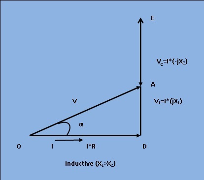
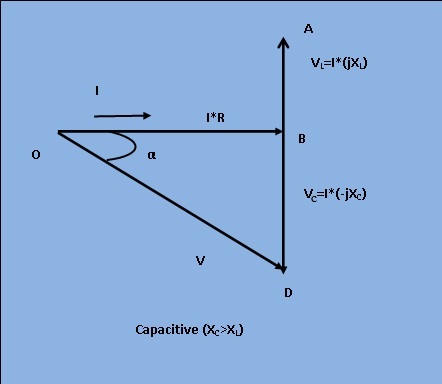
Phasor Diagram:
The phasor diagram for Inductive and capacitive series R-L-C circuit is given in figure 2 and 3 respectively.