
R-L-C Circuit Analysis 
Procedure
Circuit Diagram:
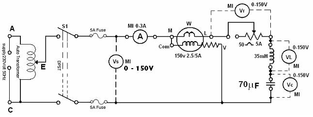
- Connect the circuit as shown in the diagram in figure 1.
- Adjust the rheostat for maximum resistance and the auto transformer to the position of zero-output voltage and switch on the supply.
- Adjust the voltage across the circuit to about 70 V and note I, Vs, VL, VC, VR and W.
- Adjust the rheostat for several settings and repeat step 3.
- Adjust the rheostat to the maximum setting and change the capacitance to 140 μF and repeat step 4.
- Compare the values of phase angle as obtained from the meter readings and from the phasor diagrams. (From the phasor diagrams compute cosθ and θ). Draw phasor diagrams showing I, Vs, VL, VC, VR for different sets of readings.