
Performance measurement and analysis of isolated DC-DC push-pull regulator
Refer Fig. 1 to answer the following questions.
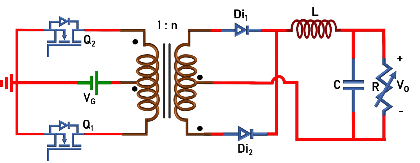
Fig. 1. Circuit configuration of push-pull converter.
1. The voltage stress of the switches (Q1 and Q2) is:
Fig. 1. Circuit configuration of push-pull converter.
1. The voltage stress of the switches (Q1 and Q2) is:
2. During dead time, the status of the switches (Q1 and Q2) and the diodes (Di1, Di2) are :
3. A push-pull converter is delivering an output power of 2 kW at an efficiency of 95%. Calculate the total losses (PLoss) occurring in the converter.
4. The inductor ripple current expression is
5. What is the voltage across the switches (Q1 and Q2) when both the diodes (Di1, Di2) are conducting?