
Norton's theorem
Theory
Norton's Theorem:
Norton's theorem states that a network consisting of several voltage sources, current sources, and resistors with two terminals is electrically equivalent to an ideal current source INO and a single parallel resistor RNO. The theorem can be applied to both A.C. and D.C. cases.
The Norton equivalent of a circuit consists of an ideal current source in parallel with an ideal impedance (or resistor for non-reactive circuits).
Norton Equivalent Circuit:
The Norton equivalent circuit is a current source with current INO in parallel with a resistance RNO. To find its Norton equivalent circuit:
- Find the Norton current (INO):
Calculate the output current, IAB, when a short circuit is the load (i.e., 0 resistance between A and B). This current is INO. - Find the Norton resistance (RNO):
If there are no dependent sources, you can use one of the following methods:- Calculate the output voltage, VAB, under open circuit condition (no load connected). Then, RNO = VAB / INO.
- Replace independent voltage sources with short circuits and independent current sources with open circuits. Then calculate the resistance seen at the output terminals; this is RNO.
- When dependent sources are present:
Use the general method:- Connect a 1 Ampere constant current source across the output terminals.
- Calculate the resulting voltage across this source.
- The Norton resistance is RNO = V / 1 A.
- This method is valid for all circuits and is required when dependent sources exist.
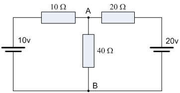
Example 1:
Consider this circuit –
To find the Norton’s equivalent of the above circuit, we first remove the center 40Ω load resistor and short the terminals A and B. This gives us the following circuit:
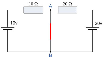
When the terminals A and B are shorted together, the two resistors are connected in parallel across their respective voltage sources. The currents flowing through each resistor, as well as the total short-circuit current, can now be calculated as:
therefore,
If we short out the two voltage sources and open circuit terminals A and B, the two resistors are now effectively connected together in parallel. The value of the internal resistor RS is found by calculating the total resistance at the terminals A and B, giving us the following circuit:
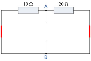
Find the Equivalent Resistance (RS):
10Ω resistor in parallel with the 20Ω resistor.
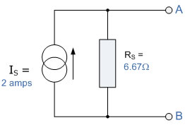
Having found both the short-circuit current, IS, and the equivalent internal resistance, RS, this gives us the following Norton's equivalent circuit:
Nortons equivalent circuit.
Ok, so far so good, but we now have to solve with the original 40Ω load resistor connected across terminals A and B, as shown below.
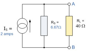
Again, the two resistors are connected in parallel across the terminals A and B, which gives us a total resistance of:
The voltage across the terminals A and B with the load resistor connected is given as:
Then the current flowing in the 40Ω load resistor can be found as:
Verification of Norton’s Theorem using the simulator:
Step 1: Create the actual circuit and measure the current across the load points.

Step 2: Create the Norton’s equivalent circuit by first creating a current source of the required equivalent current in amperes (2 A in this case), and then measure the current across the load using an ammeter.

In both cases, the current measured across the resistance should be the same.
More about Norton’s Theorem:
- Norton’s theorem and Thevenin’s theorem are equivalent, and this equivalence leads to source transformation in electrical circuits.
- For an electric circuit, the equivalence is given by:
VTh = INo × RTh
i.e., Thevenin’s voltage = Norton’s current × Thevenin’s resistance - The applications of Norton’s theorem are similar to those of Thevenin’s theorem. The main application is the simplification of electrical circuits using source transformation.