
Verification of Maximum Power Transfer Theorem 
Theory
Maximum power is transferred from a source of given voltage and an internal impedance to the load impedance ZL in the following circuit shown in figure 1, under three conditions.
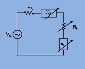
[Fig 1: Circuit diagram with source and load impedance(i.e. ZS and ZL )]
1. When only XL is adjustable:
Under this condition the power consumed by the load (I2*RL) is maximum, when I is maximum, since RL is constant.
$$ I= \frac{V_s}{R_s + jX_s + R_L + jX_L } . . . (1) $$
$$|I|_{max} = \frac{V_s}{R_s+R_L} . . . . . . . . . . . (2) $$
when $$X_L = -X_s$$
This means that if the load reactance(XL) is made equal magnitude and opposite in sign to the internal reactance(Xs), the power transferred is maximum.
2. When only RL is adjustable:
From equation (1) in section (1), one may write,
$$ P = |I^2|* R_L = \frac{V_s^2 * R_L}{(R_s + R_L)^2 + (X_s + X_L)^2} . . . (3) $$
Differentiating the equation (3) w.r.t RL and equating to zero, one obtains.
$$ R_L = \sqrt{R_s^2+ (X_s+X_L)^2}. . . . . . . . . . . . . . . . . . . (4) $$
3. When both RL and XL are adjustable:
Under this condition both equation (2) and (4) are valid simultaneously and one obtains.
$$ R_L = R_s $$
$$ X_L = -X_s $$