Interfacing of Analog Sensors
Theory
A temperature sensor is a device that detects and measures the heat energy of an object or environment. The LM35 is a precision integrated-circuit sensor that outputs a voltage linearly proportional to the Celsius temperature. Its easy-to-use analog output makes it an ideal sensor for hobbyist projects. In this project, we are creating an automated control system where temperature serves as the main input.
• LM35 Temperature Sensor : This sensor directly measures the temperature and outputs an analog voltage. This voltage is read by the Arduino's analog pin, which then converts the raw value into a precise temperature reading.
LM35 Sensor Specifications : The LM35 has a wide measurement range of -55°C to +150°C and an accuracy of +/- 0.5°C at 25°C. Its output scale factor is 10mV/°C, meaning for every 1°C increase in temperature, the output voltage rises by 10mV. The sensor operates on a supply voltage between 4V and 30V, making it perfectly compatible with the Arduino's 5V supply.
To convert the raw sensor value into a real-world temperature reading, a two-step formula is used:
First, the analogRead() function reads a value between 0 and 1023 (representing 0V to 5V). To convert this raw value into a voltage, the following formula is used: Voltage = (analogRead(A0) / 1024.0) * 5.0. Here, 1024.0 is the 10-bit resolution of the Arduino's analog-to-digital converter, and 5.0 is the Arduino's operating voltage.
Next, this voltage is converted to a temperature reading in Celsius. Since the LM35 outputs 10 mV for every 1°C of temperature, the voltage (in Volts) is simply multiplied by 100 to get the temperature value: Temperature (°C) = Voltage * 100.
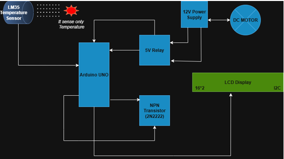
• Arduino Uno: This microcontroller acts as the brain of the project. It reads the analog input from the LM35 sensor and processes it according to the program's logic. Based on a set temperature threshold (e.g., 40°C), it decides whether to turn the outputs ON or OFF.
• LCD Display: A 16x2 I2C LCD is used to provide visual feedback. It displays the live temperature reading and the status of the motor and LED, making it easy to monitor the system.
• Relay and Transistor: A 12V DC motor requires more power than the Arduino can provide. This is where a relay is essential. A 5V relay is an electromechanical switch that is activated by a small electrical signal. The relay itself is driven by a transistor (like a 2N2222 NPN), which acts as a current amplifier. This setup allows the Arduino's low-power signal to safely control the high-power motor circuit, providing crucial electrical isolation. To protect the transistor from voltage spikes when the relay turns off, a flyback diode is often used across the relay coil.
Components Used in this Project
- Microcontroller: Arduino Uno
- Input Device: LM35 Temperature Sensor
- Output Devices: 12V DC Motor, Red LED, 16x2 LCD Display (I2C)
- Interface Components: Relay: 5V Relay Module Transistor: 2N2222 NPN Transistor Resistors: 220Ω (for LED), 1kΩ (for transistor)
- Power Sources: 12V DC Power Supply and 5V DC Power Supply (from Arduino).
Microcontroller Connections
The microcontroller acts as the central control unit, receiving input from the sensor and sending output signals to the devices. • LM35 Sensor: The LM35 temperature sensor is connected to the A0 analog I/O pin of the Arduino, and the pin is configured as a digital input pin to sense the sensor output as a logic HIGH or logic LOW as per the sensor activation. • LED and Relay: The output is connected to an NPN transistor to drive the relay, where a +12V DC motor is connected as an output device. Similarly, the RED LED is also connected as an output device.