
Directional Coupler Characteristics.
Introduction
A Directional coupler is a device that samples a small amount of Microwave power for measurement purposes. The power measurements include incident power, reflected power, VSWR values, etc. Directional Coupler is a 4-port waveguide junction consisting of a primary main waveguide and a secondary auxiliary waveguide. The following figure shows the image of a directional coupler.
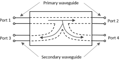
Fig. 1 Directional Coupler
Properties of Directional Couplers
The properties of an ideal directional coupler are as follows
All terminations are matched to the ports.
When power travels from Port 1 to Port 2, a portion of it couples to Port 4 but not to Port 3.
As it is a bi-directional coupler, when power travels from Port 2 to Port 1, a portion of it couples to Port 3 but not to Port 4.
If power is incident through Port 3, a portion of it couples to Port 2 but not to Port 1.
If power is incident through Port 4, a portion of it couples to Port 1 but not to Port 2.
Port 1 and Port 3 are decoupled, as are Port 2 and Port 4.
Ideally, the output of Port 3 should be zero. However, in practice, a small amount of power, known as back power, is observed at Port 3. The figure below illustrates the power flow in a directional coupler.
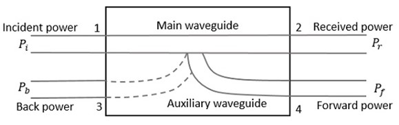
Fig. 2 Directional Coupler Indicating Powers
Where
- Pi = Incident power at Port 1
- Pr = Received power at Port 2
- Pf = Forward coupled power at Port 4
- Pb = Back power at Port 3
Following are the parameters used to define the performance of a directional coupler.
1. Coupling Factor (C)
The Coupling factor of a directional coupler is the ratio of incident power to the forward power, measured in dB.
To express the coupling factor (C) in terms of voltage (V), assuming voltage is proportional to power (since 𝑃∝𝑉2),
2. Directivity (D)
The Directivity of a directional coupler is the ratio of forward power to the back power, measured in dB.
The Directivity (D) in terms of voltage (V) can be written as:
3. Isolation (I)
It defines the directive properties of a directional coupler. It is the ratio of incident power to the back power, measured in dB.
The Isolation (I) in terms of voltage (V) can be written as:
Component List
Klystron Power Supply
Provides the necessary high voltage and current to the klystron tube, which generates the microwave signals required for the directional coupler tests.Klystron Mount
Holds the klystron securely in place, ensuring stability and proper alignment with other components during experiments.Isolator
Prevents reflected signals from returning to the klystron, protecting it from potential damage and ensuring stable operation by maintaining unidirectional signal flow.Attenuator
Allows for precise control of the microwave signal power entering the directional coupler, enabling adjustments to analyze the effects of varying input power on the coupler's performance.Multi-hole Directional Coupler
A microwave device that samples a portion of the input signal while allowing the majority to pass through. It is key for studying the coupling factor and isolation characteristics of the coupler.Matched Termination
Absorbs any excess microwave power at the unused port of the coupler, preventing reflections and ensuring accurate measurements of the coupled and transmitted signals.Detector Mount
Holds the detector that measures the output power from the coupler, providing essential data for calculating the coupling factor and assessing the performance of the directional coupler.Cathode Ray Oscilloscope (CRO)
Visualizes the output signal waveforms, allowing for analysis of amplitude, frequency, and phase relationships, which are critical for evaluating the characteristics of the directional coupler.
Block Diagram
For V1 Voltage:
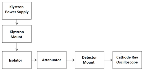
Fig. 3 Bench setup for V1 Voltage
For Coupling Factor:
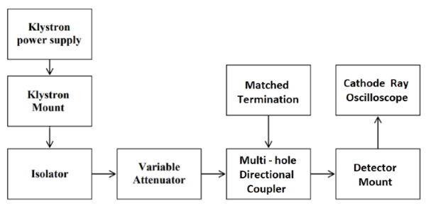
Fig. 4 Bench setup for coupling factor
For Directivity:
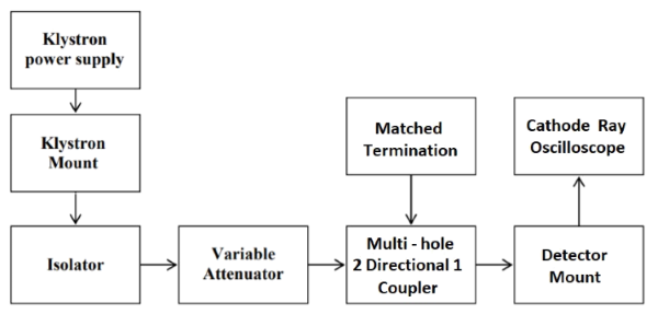
Fig. 5 Bench setup for directivity