Design of synchronous FSM 
Theory:
A synchronous Finite State Machine (FSM) is a digital circuit where state transitions are controlled by a central clock signal, occurring only at precise moments like a clock's rising or falling edge. These FSMs use flip-flops to store the current state, and their behaviour is defined by the current state and any new inputs.
Key characteristics
- Clock-controlled:
Transitions between states are synchronized to a global clock signal, ensuring orderly and predictable operation.
- Flip-flops:
State memory is held in registers (typically flip-flops) that update their values only on the triggering edge of the clock signal.
Two types of FSMs:
- Moore: Outputs are determined solely by the current state.
- Mealy: Outputs are determined by both the current state and the current inputs.
To design a synchronous finite state machine, following steps are followed.
- Word Statement of The Problem
- Design State Diagram
- Design State Table
- Reduced Standard Form State Table
- Develop State Assignment, Transition and Output Table
- Choose Flip-Flop type, form the excitation table
- Solve k-maps and develop minimal expressions.
- Implement the expressions.
Here are the steps to build a binary adder using the above steps. Ref. https://www.slideshare.net/adarshpatel2/synchronous-state-machine-design
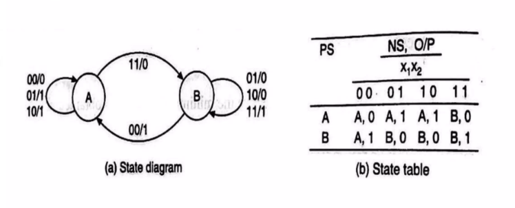
- State Diagram & State Table
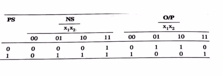
- Reduced Standard Form State Table
- Expression reduction using K-maps.
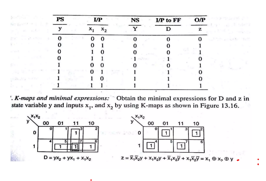
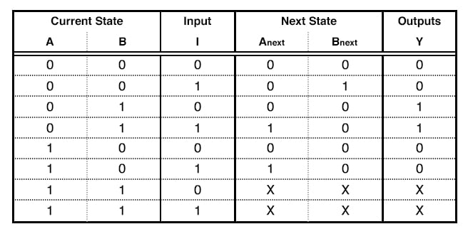
- Truth table
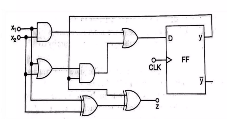
- Implementation using D Flip-Flop