
Design of synchronous FSM 
Procedure
Simulation of the circuit design in Theory Section
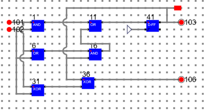
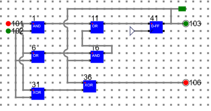
In the circuit:
Input Bits: 101 and 102
Output Bit: 106
Next State Bit: 103
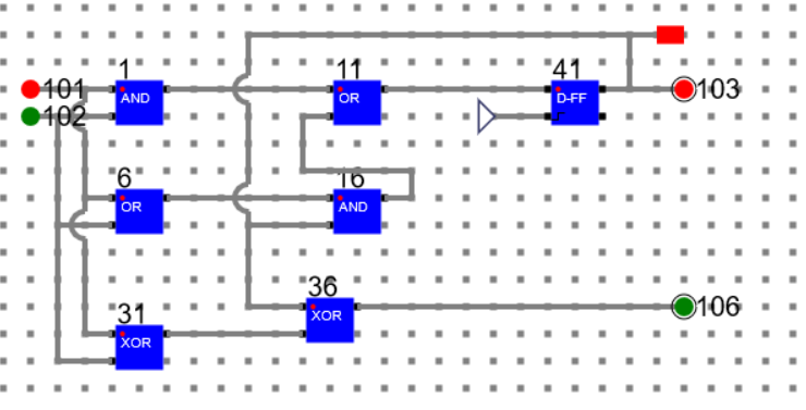
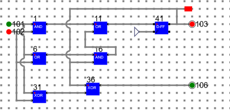
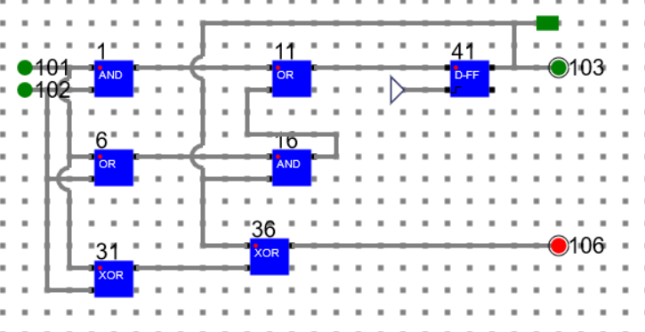
Below are the transition and output for Present State: 0 (A)
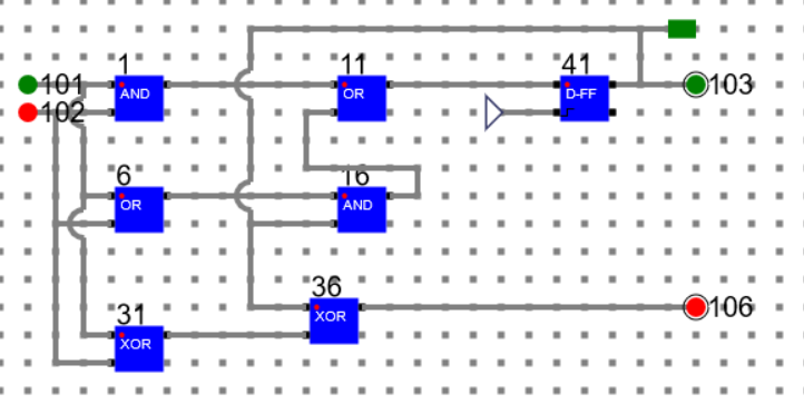
Present State: 0, Input 00, Next State: 0, Output: 0
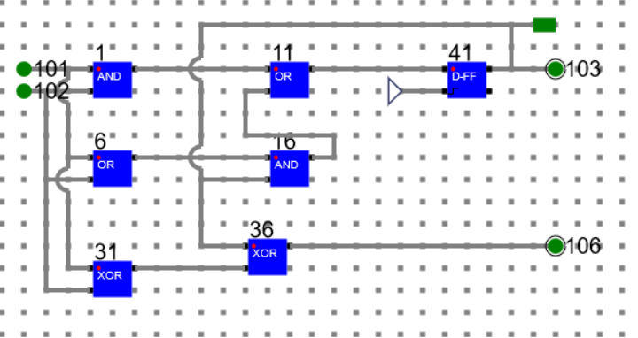
Present State: 0, Input 01, Next State: 0, Output: 1
Present State: 0, Input 10, Next State: 0, Output: 1
Present State: 0, Input 11, Next State: 1, Output: 0
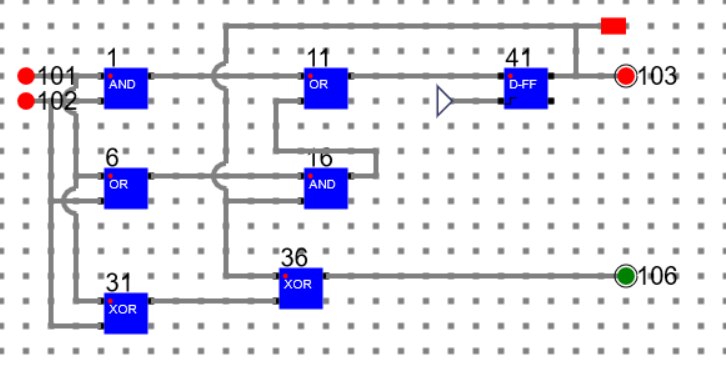
Below are the transition and output for Present State: 1 (A)
Present State: 1, Input 01, Next State: 1, Output: 0
Present State: 1, Input 10, Next State: 1, Output: 0
Present State: 1, Input 11, Next State: 1, Output: 1
Present State: 1, Input 00, Next State: 0, Output: 1
Manual
- Refer the simulator manual on how to design the circuit
- Manual --> Click Here