To design a delay timer circuit using 555 timer IC.
- Click on the Components button to place components on the table.


Fig. 1 Components
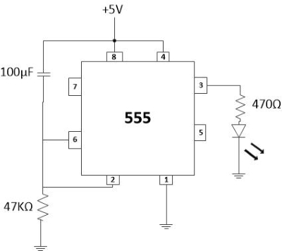
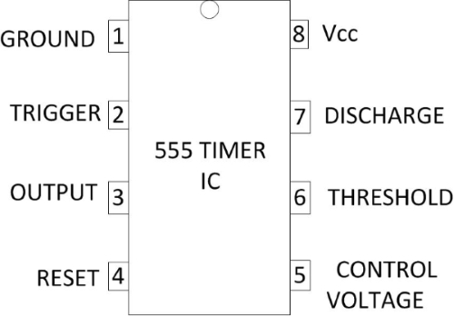
- Make connections as per the circuit diagram and pin diagram of IC or according to connection table.

Fig. 2 Circuit Diagram of Delay Before Turn On Timer

Fig. 3 Pin Diagram of 555 Timer IC
Table 1: Connection table

- Click on Check Connections button. If connections are right, click on ‘OK’, then Simulation will become active.
- Observe the Delay Time before the circuit turns on (LED glows).
- Compare it with the theoretical value.
- Click on the Reset button to reset the page.
