
Comparator
1-bit Comparator
Circuit Diagram
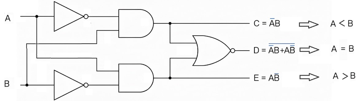
Figure 1: 1-bit Comparator circuit diagram showing logic gates for A > B, A = B, and A < B outputs. Reference: Theory section
Components Required
- 4 AND gates
- 1 OR gate
- 2 NOT gates
Circuit Connections
- Drag the first NOT gate and connect its input with B input. This creates B̄ (NOT B).
- Drag the first AND gate and connect its inputs with A input and the output of the first NOT gate (B̄). Connect its output with the A > B output bit.
- Drag the second NOT gate and connect its input with A input. This creates Ā (NOT A).
- Drag the second AND gate and connect its inputs with the output of the second NOT gate (Ā) and B input. Connect its output with the A < B output bit.
- Drag the third AND gate and connect its inputs with A input and B input.
- Drag the fourth AND gate and connect its inputs with outputs of both NOT gates (Ā and B̄).
- Drag the OR gate and connect its inputs with outputs of the third and fourth AND gates. Connect its output with the A = B output bit.
- Set the values of A and B inputs and click "Simulate" to observe the comparison results.
Observations
- Only one of the three outputs (A > B, A = B, A < B) will be high (1) at any given time.
- A > B output is high when A = 1 and B = 0.
- A = B output is high when both A and B have the same value (both 0 or both 1).
- A < B output is high when A = 0 and B = 1.
- If the circuit has been constructed correctly, a "Success" message will be displayed upon clicking "Submit".
2-bit Comparator (Direct Logic Implementation)
Circuit Diagram
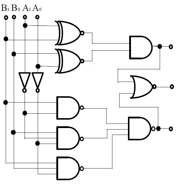
Figure 2: 2-bit Comparator circuit diagram showing hierarchical comparison logic for A₁A₀ vs B₁B₀. Reference: Theory section
Components Required
- 2 XNOR gates
- 6 AND gates
- 2 OR gates
- 2 NOT gates
Circuit Connections
For A = B Output:
- Drag the first XNOR gate and connect its inputs with A₁ and B₁ input bits.
- Drag the second XNOR gate and connect its inputs with A₀ and B₀ input bits.
- Drag an AND gate and connect its inputs with outputs of both XNOR gates. Connect its output with the A = B output bit.
For A > B Output: 4. Drag the first NOT gate and connect its input with B₁ input bit. 5. Drag an AND gate and connect its inputs with A₁ input and output of the first NOT gate. This represents A₁B₁'. 6. Drag the second NOT gate and connect its input with B₀ input bit. 7. Drag an AND gate and connect its inputs with A₀ input and output of the second NOT gate. This represents A₀B₀'. 8. Drag an AND gate and connect its inputs with outputs of both XNOR gates and the A₀B₀' term from step 7. 9. Drag an OR gate and connect its inputs with outputs from steps 5 and 8. Connect its output with the A > B output bit.
For A < B Output: 10. Drag the third NOT gate and connect its input with A₁ input bit. 11. Drag an AND gate and connect its inputs with output of the third NOT gate and B₁ input. This represents A₁'B₁. 12. Drag the fourth NOT gate and connect its input with A₀ input bit. 13. Drag an AND gate and connect its inputs with output of the fourth NOT gate and B₀ input. This represents A₀'B₀. 14. Drag an AND gate and connect its inputs with outputs of both XNOR gates and the A₀'B₀ term from step 13. 15. Drag an OR gate and connect its inputs with outputs from steps 11 and 14. Connect its output with the A < B output bit. 16. Set the values of A₁, A₀, B₁, and B₀ inputs and click "Simulate".
Observations
- A = B output is high when binary number A₁A₀ equals B₁B₀, and the other two outputs show 0.
- A > B output is high when binary number A₁A₀ is greater than B₁B₀, and the other two outputs show 0.
- A < B output is high when binary number A₁A₀ is less than B₁B₀, and the other two outputs show 0.
- The MSB comparison takes priority over LSB comparison.
- If the circuit has been constructed correctly, a "Success" message will be displayed upon clicking "Submit".
2-bit Comparator Using Subtractor
Circuit Diagram
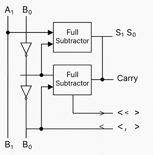
Figure 3: 2-bit Comparator using Subtractor approach showing full adders with input inversions for A₁A₀ - B₁B₀ operation. Reference: Theory section
Components Required
- 2 Full Adders
- 2 XOR gates (for B input inversion)
- 2 NOT gates (for result analysis)
- 1 AND gate (for equality detection)
Circuit Connections
Subtractor Implementation:
- Drag the first XOR gate and connect its inputs with B₀ input and logic 1 (VCC). This inverts B₀.
- Drag the second XOR gate and connect its inputs with B₁ input and logic 1 (VCC). This inverts B₁.
- Drag the first Full Adder and connect:
- A input with A₀
- B input with output of first XOR gate (B₀')
- Cin with logic 1 (for 2's complement +1)
- Sum output labeled as S₀
- Cout connected to Cin of second Full Adder
- Drag the second Full Adder and connect:
- A input with A₁
- B input with output of second XOR gate (B₁')
- Cin with Cout from first Full Adder
- Sum output labeled as S₁
- Cout labeled as C₁
Comparison Output Generation: 5. Drag the first NOT gate and connect its input with S₀. 6. Drag the second NOT gate and connect its input with S₁. 7. Drag an AND gate and connect its inputs with outputs of both NOT gates. Connect its output with A = B output bit. 8. Connect C₁ directly to A > B output bit. 9. Drag a NOT gate and connect its input with C₁. Connect its output with A < B output bit. 10. Set the values of A₁, A₀, B₁, and B₀ inputs and click "Simulate".
Observations
- The subtractor performs A₁A₀ - B₁B₀ using 2's complement arithmetic.
- A = B output is high when the subtraction result S₁ S₀ = 00 (zero result).
- A > B output is high when carry C₁ = 1 (no borrow occurred, positive result).
- A < B output is high when carry C₁ = 0 (borrow occurred, negative result).
- This method demonstrates the relationship between arithmetic and comparison operations.
- If the circuit has been constructed correctly, a "Success" message will be displayed upon clicking "Submit".
Testing Procedures
1-bit Comparator Testing
Test Case 1: A = 0, B = 0
- Expected: A = B = 1, A > B = 0, A < B = 0
Test Case 2: A = 0, B = 1
- Expected: A = B = 0, A > B = 0, A < B = 1
Test Case 3: A = 1, B = 0
- Expected: A = B = 0, A > B = 1, A < B = 0
Test Case 4: A = 1, B = 1
- Expected: A = B = 1, A > B = 0, A < B = 0
2-bit Comparator Testing
Test Case 1: A₁A₀ = 01, B₁B₀ = 10
- Expected: A = B = 0, A > B = 0, A < B = 1 (1 < 2)
Test Case 2: A₁A₀ = 11, B₁B₀ = 10
- Expected: A = B = 0, A > B = 1, A < B = 0 (3 > 2)
Test Case 3: A₁A₀ = 10, B₁B₀ = 10
- Expected: A = B = 1, A > B = 0, A < B = 0 (2 = 2)
Troubleshooting
- No Output Active: Check that all gate connections are properly made and inputs are set correctly.
- Multiple Outputs Active: Verify the logic gate connections, particularly the NOT gates and their connections.
- Incorrect Comparison Results: For 2-bit comparator, ensure XNOR gates are used for bit equality and priority logic is correctly implemented.
- Subtractor Method Issues: Verify that B inputs are properly inverted and the +1 for 2's complement is applied to the first Full Adder's Cin.