
Characteristics of Avalanche Photo Diode (APD).
Procedure
- Make the set-up as in the diagram and connect the 1KΩ resistor across VL.
- set the bias voltage at 10 V.
- Set the power source in CW mode and adjust to get maximum output. Connect the 1m ST-ST patch cord between source and power meter and adjust the power to -18dBm.
- Connect the optical fiber cable to the PD module and measure the voltage across RL[1KΩ] and note as VL.
- Vary the bias voltage from 10 V in steps of 20 V up to 140 V and note down the corresponding VL.
- Calculate IR = VL / (1 x 10³ ).
- Plot the graph : VBIAS Vs IR.
- Repeat steps 4 to 7 for different input powers say -25 dBm, -40 dBm, etc.
- Calculate the responsivity from : Rλ = VL /(RL*PS) A/W where PS is the power in Watts.
- From the average value of Rλ, calculate the quantum efficiency using: ηC = (Rλhν/e) x 1/100 % where h=6.63 x 10⁻³ Js; e = 1.6 x 10⁻¹⁹ C; ν = c/λ = 3 x 10⁸/λ
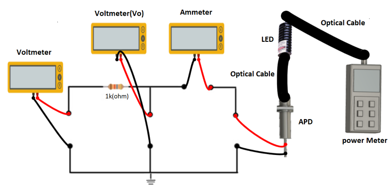
Figure 1: Set up for Characteristics of Avalanche Photo Diode (APD)