
Bipolar PWM Single Phase Inverter with RL Load
Introduction
A bipolar PWM single-phase inverter is a type of power electronic device used to convert DC (direct current) power into AC (alternating current) power with a single-phase output. It utilizes a pulse width modulation (PWM) technique to control the switching of power semiconductor devices, typically insulated gate bipolar transistors (IGBTs) or MOSFETs (Metal-Oxide-Semiconductor Field-Effect Transistors).
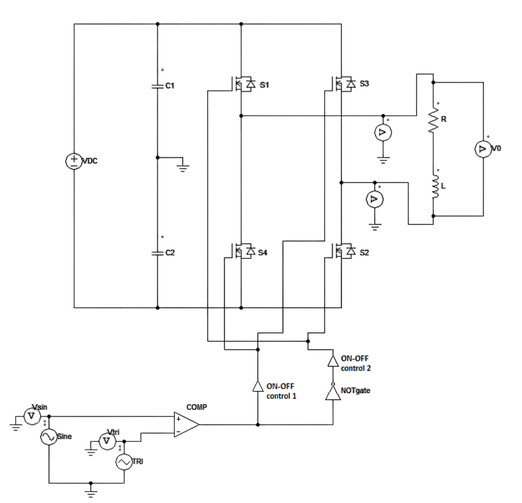
The bipolar PWM inverter produces an AC output waveform by switching the DC input voltage between positive and negative polarities. It generates the desired AC output voltage by varying the width of the pulses while maintaining a fixed frequency. By adjusting the pulse width, the inverter can regulate the amplitude of the output voltage, the operation of a bipolar PWM single-phase inverter involves dividing the input DC voltage into several voltage levels and then applying suitable pulse width modulation techniques to obtain the desired AC output waveform. This is achieved by comparing a reference sinusoidal waveform with a triangular waveform generated by a carrier signal. The inverter generates the necessary pulses to approximate the reference waveform based on the comparison.
Pulse-Width Modulated Inverters
PWM Inverter uses PWM (Pulse Width Modulation) technique to control the output voltage of the inverter, this is done to fulfill the AC load requirements. In PWM inverter the controlled output is obtained by adjusting the ON and OFF period of the inverter components.
Pulse-width modulation is used in inverters for the purpose of regulating the amplitude and the frequency of the output voltage. In the inverter circuits, it is even more complex because it is required that one obtains approximately sinusoidal voltage of a preassigned frequency (usually 50 or 60 Hz) at its output.
The pulse-width-modulated (PWM) inverters use a harmonic control (modulating) signal, whereas the carrier signal is triangular.
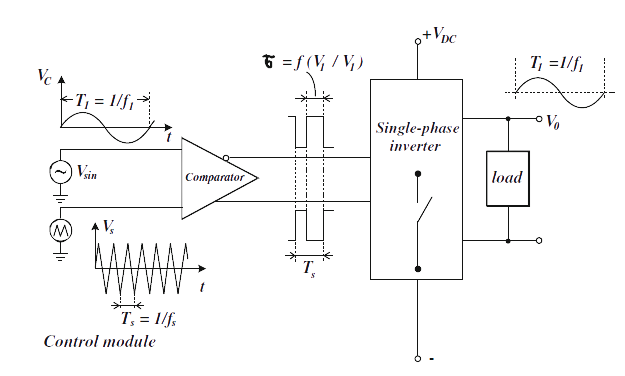
A PWM module consists of:
• a sinusoidal oscillator with a frequency f1 (normally 50 or 60 Hz) which generates the control signal.
• a generator of triangular voltage (carrier signal) whose frequency fs is several times higher than f1.
• a comparator with complementary outputs as shown in Fig. 2.
The pulse frequency at the comparator output is equal to the frequency of the carrier signal fs, and the duration of the pulses depends on the ratio of the instantaneous values of the voltages of the control and carrier signals. Since these pulses control the states of the inverter switches, the switches will also operate at the frequency fs modulated by the ratio of the turn-on and the turn-off time. Consequently, it follows that
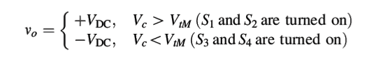
Since the output voltage varies between +VDC and –VDC and vice-versa so the PWM technique are called bipolar modulators. Because the frequency of the carrier signal is much higher than the frequency of the sinusoidal control signal, i.e., fs >> f1.
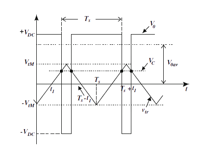
It may be assumed that the control voltage Vc during the cycle Ts is approximately constant. Then, based on Fig. 3, the average value of the output voltage is
$$V_{oav} = \frac {1}{T_s} \biggr[ \int_{t_1}^{T_s-t_1}-V_{DC} ~ dt + \int_{T_s-t_1}^{T_s+t_1}V_{DC} ~ dt \biggr].........(1)$$
Because in the interval 0 ≤ t ≤ Ts
$$V_{tr} = −V_{tM}+ \left(\frac {4V_{tM}}{T_s}\right)t$$
From the condition
$$V_{tr}(t1) = V_c$$
It follows that
$$t_1 = \frac {T_s}{4} \biggr(1+ \frac {V_c}{V_{tM}} \biggr).......(2)$$
From equation (1) and (2) it follows that
$$V_{oav} = \frac {V_{c}}{V_{tM}}V_{DC}.........(3)$$
Here VtM is maximum value of triangular wave
If
$$V_c = V_{cM} \ sin(\omega t).........(4)$$
Here VcM is maximum value of carrier wave
Then
$$V_{oav} = \frac {V_{cM}}{V_{tM}}V_{DC} ~ sin(\omega t) = m_a V_{DC} ~ sin(\omega t).........(5)$$
Where,
$$m_a= \frac {V_{cM}}{V_{tM}} ..........(6)$$
Here, ma is the factor of amplitude modulation, equal to the ratio of the sinusoidal control signal and the triangular carrier signal. On the basis of Equation (5) one can draw a very important conclusion that the average value of the output voltage is a sinusoidal function having the frequency of the control signals f1 (dashed line in Fig. 4 (b)) and the amplitude
$$V_{oM} = m_a V_{DC} \le V_{DC}..........(7)$$
because the amplitude modulation factor ma < 1.
In addition to the factor of amplitude modulation we must remember the harmonics frequency is given by
$$f_h = h.f_1 ..........(8)$$
Where fh is harmonic frequency, f1 is fundamental frequency
Here h = 3, 5, 7, 9..........
As far as harmonic is concern
$$h = (j.m_f \pm k)$$
Where mf is an carrier ratio i.e.,
$$m_f = \frac {f_s}{f_1} ..........(9)$$
Where fs is switching frequency and f1 is fundamental frequency.
So,
$$f_h = (j.m_f \pm k) f_1 ..........(10)$$
Note: For odd value of j, k will be even and for even value of j, k will be odd value.
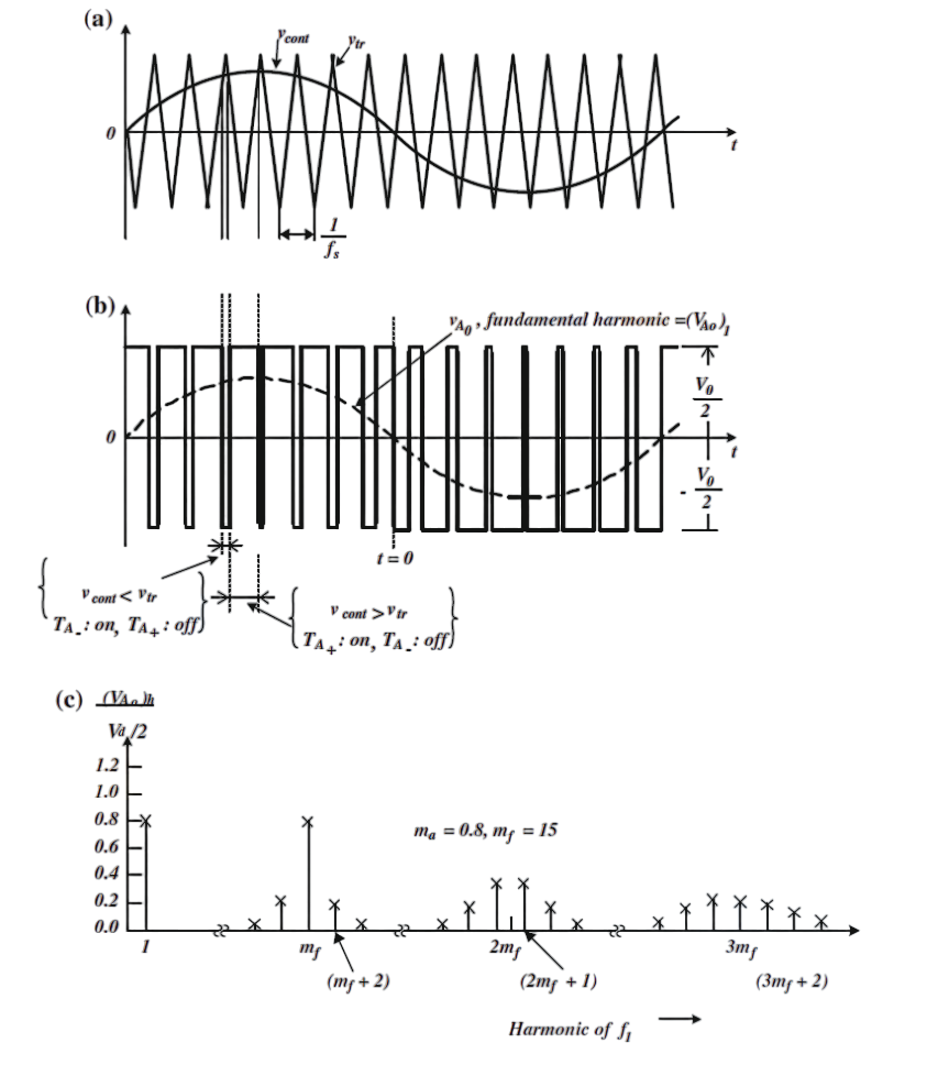
Even though mf >> 1, the control signal is not constant within one cycle Ts. For this reason the output voltage will contain higher harmonics, whereas (5) gives its fundamental harmonic. The higher harmonics appear around the carrier frequency as shown in Fig. 4(c) and its integer multiples, more precisely around the harmonics mf, 2mf, 3mf, … For instance, if mf = 15, harmonics 15, 17, 13, …, 31, 33, 29, etc. will exist.
Advantages of Bipolar PWM single-phase inverter
- Better voltage waveform quality: The PWM technique allows for precise control of the output voltage waveform, resulting in lower harmonic distortion and better overall waveform quality.
- Improved efficiency: The use of power semiconductor devices with low conduction and switching losses, such as IGBTs or MOSFETs, helps in achieving higher efficiency.
- Enhanced voltage regulation: The pulse width modulation technique enables effective voltage regulation, allowing the inverter to maintain a stable output voltage despite changes in load conditions.
- Flexibility: Bipolar PWM single-phase inverters can be used in a variety of applications, including motor drives, renewable energy systems, uninterruptible power supplies (UPS), and more.
Disadvantages of Bipolar PWM single-phase inverter
- Increased harmonic content: Bipolar PWM techniques generate more harmonic distortion compared to other PWM techniques.
- Higher switching losses: Bipolar PWM requires switching between positive and negative half-cycles of the output waveform. This introduces additional switching losses compared to unipolar PWM, where switching occurs only in one polarity.
- Complex control circuitry: Bipolar PWM inverters typically require more complex control circuitry compared to unipolar PWM inverters.
- Increased voltage stress on components: The rapid switching between positive and negative voltages can lead to increased voltage spikes and transients, which can degrade the reliability and lifespan of the components.
Applications of Bipolar PWM single-phase inverter
- Bipolar PWM inverters are extensively used in motor drives for controlling the speed and torque of electric motors.
- Bipolar PWM inverters play a crucial role in renewable energy systems such as solar power and wind power. They convert the DC power generated by solar panels or wind turbines into AC power suitable for grid integration or powering local loads.
- UPS systems are used to provide backup power during utility power outages. Bipolar PWM inverters are employed in UPS systems to convert DC power from batteries into AC power to supply critical loads.
- Bipolar PWM inverters are used in power factor correction circuits to improve the power quality in electrical systems. By controlling the switching frequency and duty cycle of the PWM signals, the inverter can shape the input current waveform, reducing harmonics and improving the overall power factor.
- Bipolar PWM inverters are employed in EV charging stations to convert AC power from the grid into DC power for charging the vehicle's battery.