Verifying Bernoulli's energy equation
1. Introduction
Bernoulli’s theorem mathematically provides insight in understanding the fluid mechanics. Bernoulli’s equation is applicable to many real-world applications, for e.g. understanding aerodynamics of car, airplane; wind loading on civil structures like buildings, towers; city sewer and water networks; flow measurement devices like venturi meters, etc. Even though the mathematical expression for Bernoulli’s theorem is simple but the principle plays major roles in the technology and designing to improve human life.
2. Components of Experimental setup
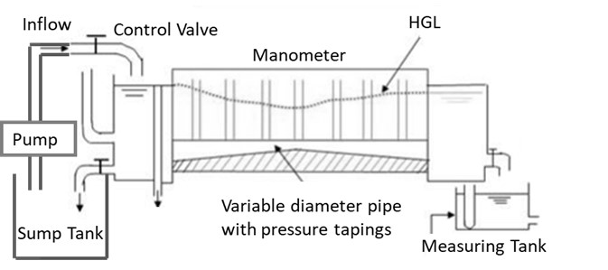
Fig. 2, shows a schematic of test rig or bench to validate Bernoulli’s equation in a variable diameter pipe, whose each part is explained as follows :
2.1 Flow Meter
The test bench consists of flow meter for the experiments. The meter shows the amount of water flowing through the pipe
2.2 Control Valve
A Control valve is provided through which the flow rate of the water flowing through the pipes is controlled.
2.3 Variable Diameter Pipe
A variable diameter acrylic pipe is the test section where manometers are attached at various cross-sections to note down pressure head.
2.4 Measuring Tank
Measuring tank with gauge glass and scale arrangement for quick and easy measurement to determine height of water filled in the tank.
2.5 Manometer
Pressure tappings are provided across the length of the variable diameter pipe. The reading of the pressure tapings will provide the pressure head at various locations across the length of the pipe.
2.6 Sump
Sump is provided to store sufficient water for independent circulation through the unit for experimentation and arranged within the floor space of the main unit
3. Theory
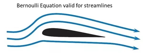
Bernoulli’s equation assumes that the fluid flow is steady, incompressible and friction losses are negligible. These assumptions are also based on the laws of conservation of mass and energy. It can be applied between any two points in the flow field, if the flow is irrotational. However, for the rotational flow, the two points must lie in the same streamline. Bernoulli’s equation states that the “sum of the kinetic energy (velocity head), the pressure energy (static head) and Potential energy (elevation head) per unit weight of the fluid at any point remains constant” provided the flow is steady, irrotational, and frictionless and the fluid used is incompressible. This is however, on the assumption that energy is neither added to nor taken away by some external agency. The key approximation in the derivation of Bernoulli’s equation is that viscous effects are negligibly small compared to inertial, gravitational, and pressure effects
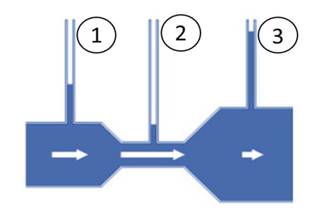
For example, in Fig. 3 the flow passing through three consecutive pipes i.e pipe 1, pipe 2 and pipe 3
On applying the theorem for section 1,2 and 3 (see Fig. 3) as:
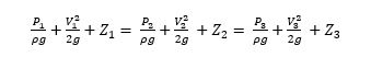
Where frictional losses hf = 0, is assumed to be negligible as compared to inertial, gravitational and pressure effects.
Since pipe is horizontally placed hence, Z1=Z2=Z3 , hence:
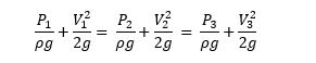
Or rewriting the above equation:
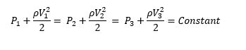
● P is the static pressure since it does not incorporate any dynamic effects
● (ρV2)/2 is the dynamic pressure
● ρgZ is the hydrostatic pressure (is omitted in this case as pipe is horizontally placed). Its value depends on the reference level selected; it accounts for the elevation effects
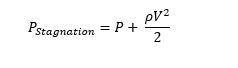
The sum of the static, dynamic pressures and hydrostatic pressure is called the total pressure. In other words, the Bernoulli equation states that the total pressure along a streamline is constant. The sum of the static and dynamic pressures is called the stagnation pressure, and it is expressed as: