Verifying Bernoulli's energy equation
Procedure
The following steps are to be followed to validate Bernoulli’s equation:
- Check whether all the joints and the sump are not leaking
- Fill in the sump tank with clean water
- Keep the delivery valve closed
- Check and give necessary electrical connections to the system
- Switch on the pump & slowly open the delivery valve
- Adjust the flow through the control valve of the pump
- Allow the system to attain the steady state. i.e, let the water pass from second overhead tank to the collecting tank
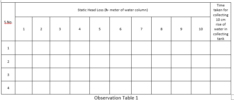
- Note down the pressure head at different points of the venturi meter on the multitube piezometer. (Expel if any air is the by inserting the thin pin into the piezometer openings)
- Close the ball valve of the collecting tank and measure the time for the known rise of water.
- Change the flow rate and repeat the experiment
Formulae
- Calculate Actual Discharge (Qact)
Note down the time required for the rise of 10 cm (i.e. 0.1 m) water in the collecting tank by using stop watch. Calculate discharge using below formulae:
Discharge: The time taken to collect some ‘R’ cm of water in the collecting tank
Qact=((A×R)/t)
A = area of the collecting tank in m²
R = rise of water level taken in meters (say 0.1 m or 10 cm)
t = time taken for the rise of water level to height ‘R’ in seconds
Pressure head = P/ρg = h (m of water)
ρ = Density of water in Kg/m3
g = Acceleration due to gravity in m/s²
h = Head measured in water column in m
- Calculate the velocity head:
Velocity head=V2/2g
A = Cross sectional area of the pipe at a given water column = (πD2)/4
- Validation of Bernoulli’s Equation:
After estimating pressure head and velocity head at various cross sections of variable diameter pipe, the summation of both should be constant i.e.

Observations –
- Area of the tank (A) = 0.45 m2

