
Adder Circuit
Half Adder

A half adder adds two 1-bit binary numbers A and B to generate a 1-bit SUM (S) and a 1-bit CARRY (C) as output. The carry is theoretically carried on to the next bit position. The decimal equivalent of the sum of A and B numerically equals 2×C + S. The simplest half-adder design, as shown in the above figure, incorporates an XOR gate for S and an AND gate for C.
Logic Equations
The outputs S and C can be expressed as logical functions of input variables A and B as follows:
S = A ⊕ B (XOR gate)
C = A · B (AND gate)
Key Features
- Simple design using only XOR and AND gates
- Adds two 1-bit numbers
- Produces sum and carry outputs
- Cannot be cascaded due to lack of carry-in input
- Foundation for more complex adder circuits
Truth Table
| A | B | CARRY | SUM |
|---|---|---|---|
| 0 | 0 | 0 | 0 |
| 0 | 1 | 0 | 1 |
| 1 | 0 | 0 | 1 |
| 1 | 1 | 1 | 0 |
Applications
- Basic building block for arithmetic circuits
- Simple calculator designs
- Educational demonstrations of binary addition
- Component in more complex adder designs
Full Adder

A full adder adds two 1-bit binary numbers along with a carry generated from the previous addition and produces a sum and carry as outputs. A 1-bit full adder adds three 1-bit numbers, often written as A, B, and Cin, where A and B are the operands, and Cin is a bit carried in from a previous addition. The decimal equivalent of the sum equals 2×Cout + S.
Logic Equations
S = A ⊕ B ⊕ Cin
Cout = A · B + Cin · (A ⊕ B)
Key Features
- Accepts three inputs: A, B, and carry-in (Cin)
- Produces sum (S) and carry-out (Cout)
- Can be cascaded to create multi-bit adders
- Essential building block for ripple carry adders
- More complex than half adder but more versatile
Truth Table
| A | B | Cin | Cout | S |
|---|---|---|---|---|
| 0 | 0 | 0 | 0 | 0 |
| 1 | 0 | 0 | 0 | 1 |
| 0 | 1 | 0 | 0 | 1 |
| 1 | 1 | 0 | 1 | 0 |
| 0 | 0 | 1 | 0 | 1 |
| 1 | 0 | 1 | 1 | 0 |
| 0 | 1 | 1 | 1 | 0 |
| 1 | 1 | 1 | 1 | 1 |
Applications
- Multi-bit arithmetic operations
- Processor arithmetic logic units (ALUs)
- Digital signal processing systems
- Binary calculator circuits
- Computer arithmetic units
Ripple Carry Adder
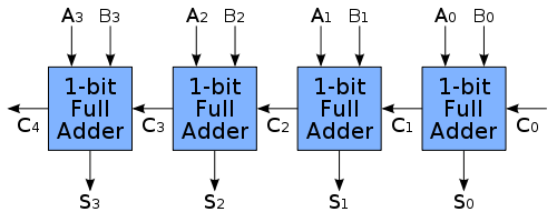
Multiple full adders can be used to create adders of greater bit lengths. Each full adder uses the Cout of the previous adder as its Cin. This kind of adder is called a ripple carry adder, since the carry bits "ripple" through the full adder stages from right to left (LSB to MSB). Note that the first (and only the first) full adder may be replaced by a half adder.
Understanding Circuit Layout vs. Computational Flow
Traditional Mathematical Notation: Binary numbers are typically written with MSB (Most Significant Bit) on the left and LSB (Least Significant Bit) on the right, such as A₃A₂A₁A₀ for a 4-bit number.
Computational Flow in Ripple Carry Adders: However, the actual addition computation starts from the LSB and propagates toward the MSB. This is because:
- Addition begins with the rightmost (least significant) bits
- Any carry generated must propagate leftward to the next higher bit position
- The carry "ripples" from LSB→MSB (right to left in traditional notation)
Simulation Demo Layout: In our interactive simulation, the circuit is arranged with LSB (A₀,B₀) on the left and MSB (A₃,B₃) on the right to clearly visualize this computational flow from left to right on screen. This helps students understand the sequential nature of carry propagation.
Logic Equations
For a 4-bit ripple carry adder, each bit position has its own sum and carry equations. The key concept is that each stage depends on the carry output from the previous stage. The addition process flows from right to left (LSB to MSB):
Bit 0 (LSB - Rightmost):
- S₀ = A₀ ⊕ B₀ ⊕ Cin
- C₀ = A₀B₀ + B₀Cin + CinA₀
Bit 1:
- S₁ = A₁ ⊕ B₁ ⊕ C₀
- C₁ = A₁B₁ + B₁C₀ + C₀A₁
Bit 2:
- S₂ = A₂ ⊕ B₂ ⊕ C₁
- C₂ = A₂B₂ + B₂C₁ + C₁A₂
Bit 3 (MSB - Leftmost):
- S₃ = A₃ ⊕ B₃ ⊕ C₂
- C₃ = A₃B₃ + B₃C₂ + C₂A₃
Key Features
- Each sum bit (S) uses XOR of the two input bits and the carry from the previous stage
- Each carry bit (C) is generated when any two of the three inputs (A, B, Cin) are 1
- The carry "ripples" from right to left (LSB to MSB), which is why it is called a ripple carry adder
- Addition starts from the rightmost bit (LSB) and propagates leftward to the MSB
- The final carry C₃ represents an overflow if we are working with 4-bit numbers
- Simple design but slower due to carry propagation delay
Applications
- Multi-bit arithmetic in basic processors
- Simple calculator implementations
- Educational demonstrations of binary arithmetic
- Foundation for understanding faster adder designs
- Digital systems requiring multi-bit addition
Adder-Subtractor Circuit
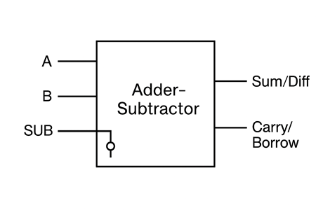
An adder-subtractor is a combinational circuit that can perform both addition and subtraction operations on binary numbers using the same hardware. This is achieved by utilizing the 2's complement method for subtraction.
Principle of Operation
Addition Mode (M = 0): The circuit performs normal binary addition. Subtraction Mode (M = 1): The circuit performs A - B by computing A + (2's complement of B).
The 2's complement of a binary number is obtained by:
- Finding the 1's complement (inverting all bits)
- Adding 1 to the result
Logic Equations
For each bit position i:
- Modified B input: B'ᵢ = Bᵢ ⊕ M
- Sum/Difference: Sᵢ = Aᵢ ⊕ B'ᵢ ⊕ Cᵢ₋₁
- Carry: Cᵢ = AᵢB'ᵢ + Cᵢ₋₁(Aᵢ ⊕ B'ᵢ)
- Initial Carry: C₀ = M
Key Features
- Single circuit performs both addition and subtraction
- Uses XOR gates to conditionally invert B inputs based on mode control M
- Mode control line M selects between addition and subtraction
- When M = 0: B inputs pass through unchanged (B ⊕ 0 = B)
- When M = 1: B inputs are inverted (B ⊕ 1 = B'), and M provides the +1 for 2's complement
- Hardware efficient design using existing full adder logic
Truth Table for Operation Mode
| M | Operation | Result |
|---|---|---|
| 0 | A + B | Sum = A + B |
| 1 | A - B | Difference = A + (2's complement of B) |
Applications
- Arithmetic Logic Units (ALUs): Essential component in processors
- Digital Signal Processing: Mathematical operations in DSP systems
- Calculator circuits: Basic arithmetic operations
- Control systems: Mathematical computations in embedded systems
- Microprocessors: Fundamental arithmetic operations in CPUs