
Decoder with 7 segment display
BCD to 7-Segment Display Decoder

A BCD to 7-segment decoder is a combinational circuit that converts a 4-bit Binary Coded Decimal (BCD) input into the appropriate output signals to drive a 7-segment display device for displaying decimal digits 0 through 9. The decoder takes four input bits (A, B, C, D) representing BCD numbers and generates seven output signals (a, b, c, d, e, f, g) to control the individual segments of a 7-segment display.
Understanding 7-Segment Display Structure
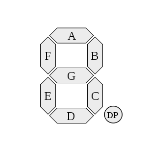
A 7-segment display consists of seven individual LED segments arranged in a figure-8 pattern, labeled as a, b, c, d, e, f, and g in a clockwise sequence starting from the top horizontal segment. Each segment can be individually controlled to display decimal digits 0-9. An optional eighth segment, the decimal point (DP), is used for displaying fractional numbers.
Key Features of 7-Segment Displays:
- Seven segments labeled a, b, c, d, e, f, g (lowercase for segment identification)
- BCD inputs labeled A, B, C, D (uppercase for binary input signals)
- Common-cathode or common-anode configurations available
- Individual segment control enables digit formation
Display Configuration Types
Common-Cathode Display: All cathodes of the seven LEDs are connected together and brought out as a single pin. To light a segment, the corresponding anode pin must be driven HIGH (logic 1). This experiment uses common-cathode configuration.
Common-Anode Display: All anodes of the seven LEDs are connected together. To light a segment, the corresponding cathode pin must be driven LOW (logic 0).
BCD to 7-Segment Truth Table
The decoder converts 4-bit BCD inputs (A, B, C, D) to 7-segment outputs (a, b, c, d, e, f, g). For common-cathode displays, a segment lights when its corresponding output is HIGH (1).
| A | B | C | D | a | b | c | d | e | f | g | Digit |
|---|---|---|---|---|---|---|---|---|---|---|---|
| 0 | 0 | 0 | 0 | 1 | 1 | 1 | 1 | 1 | 1 | 0 | 0 |
| 0 | 0 | 0 | 1 | 0 | 1 | 1 | 0 | 0 | 0 | 0 | 1 |
| 0 | 0 | 1 | 0 | 1 | 1 | 0 | 1 | 1 | 0 | 1 | 2 |
| 0 | 0 | 1 | 1 | 1 | 1 | 1 | 1 | 0 | 0 | 1 | 3 |
| 0 | 1 | 0 | 0 | 0 | 1 | 1 | 0 | 0 | 1 | 1 | 4 |
| 0 | 1 | 0 | 1 | 1 | 0 | 1 | 1 | 0 | 1 | 1 | 5 |
| 0 | 1 | 1 | 0 | 1 | 0 | 1 | 1 | 1 | 1 | 1 | 6 |
| 0 | 1 | 1 | 1 | 1 | 1 | 1 | 0 | 0 | 0 | 0 | 7 |
| 1 | 0 | 0 | 0 | 1 | 1 | 1 | 1 | 1 | 1 | 1 | 8 |
| 1 | 0 | 0 | 1 | 1 | 1 | 1 | 1 | 0 | 1 | 1 | 9 |
Segment Pattern Analysis
For better understanding, here's which segments remain OFF for each digit:
| Digit | OFF Segments | Active Segments |
|---|---|---|
| 0 | g | a,b,c,d,e,f |
| 1 | a,d,e,f,g | b,c |
| 2 | c,f | a,b,d,e,g |
| 3 | e,f | a,b,c,d,g |
| 4 | a,d,e | b,c,f,g |
| 5 | b,e | a,c,d,f,g |
| 6 | b | a,c,d,e,f,g |
| 7 | d,e,f,g | a,b,c |
| 8 | none | a,b,c,d,e,f,g |
| 9 | e | a,b,c,d,f,g |
Logic Equations
Based on the truth table, the logic equations for each segment can be derived using Boolean algebra. These equations define when each segment should be activated:
Segment a: a = A'B'C'D' + A'B'CD' + A'BCD + A'BCD' + AB'C'D' + AB'C'D
Segment b: b = A'B'C'D + A'B'CD' + A'B'CD + A'BC'D' + A'BCD + AB'C'D' + AB'C'D
Segment c: c = A'B'C'D + A'B'CD + A'BC'D' + A'BC'D + A'BCD' + A'BCD + AB'C'D' + AB'C'D
Segment d: d = A'B'C'D' + A'B'CD + A'BC'D + A'BCD' + AB'C'D' + AB'C'D
Segment e: e = A'B'C'D' + A'B'C'D + A'B'CD + A'BC'D + AB'C'D' + AB'C'D
Segment f: f = A'B'C'D' + A'B'C'D + A'BC'D' + A'BC'D + A'BCD' + AB'C'D' + AB'C'D
Segment g: g = A'B'CD + A'BC'D' + A'BC'D + A'BCD' + A'BCD + AB'C'D' + AB'C'D
Key Features
- Input: 4-bit BCD code (A, B, C, D) representing decimal digits 0-9
- Output: 7 control signals (a, b, c, d, e, f, g) for 7-segment display
- Common-cathode compatibility: Output HIGH (1) lights the corresponding segment
- Decimal display: Converts binary representation to human-readable decimal digits
- Combinational logic: Output depends only on current input state
Applications
- Digital clocks and timers: Displaying time in hours, minutes, and seconds
- Electronic calculators: Showing numerical results and intermediate calculations
- Digital voltmeters and multimeters: Displaying measured values
- Microwave ovens and appliances: Showing cooking time and settings
- Electronic scoreboards: Displaying scores in sports and games
- Frequency counters: Showing measured frequency values
- Digital thermometers: Displaying temperature readings
Decoder Implementation Methods
Direct Logic Implementation
The most straightforward approach uses individual logic gates to implement the Boolean equations for each segment. This method requires:
- Multiple AND, OR, and NOT gates
- Seven separate logic circuits (one per segment)
- Direct mapping from truth table to hardware
ROM-Based Implementation
A Read-Only Memory (ROM) approach stores the truth table directly:
- 4-bit address inputs (A, B, C, D)
- 7-bit data outputs (a, b, c, d, e, f, g)
- Compact implementation for small truth tables
- Easy modification for custom display patterns
Multiplexer-Based Implementation
Using multiplexers to select appropriate output patterns:
- Input selects which digit pattern to display
- Pre-stored patterns for each BCD input
- Efficient for multiple display applications