
Decoder with 7 segment display
BCD to 7-Segment Decoder
Circuit Diagram

Figure 1: BCD to 7-Segment Decoder circuit diagram showing the complete combinational logic implementation using logic gates. Reference: Theory section
Components Required
- 22 NOT gates
- 10 2-input NAND gates
- 23 3-input NAND gates
Circuit Connections
- Drag logic gates from the Components panel on the left side to the circuit board.
- Connect the input bits A, B, C, and D to the appropriate logic gates according to the circuit diagram.
- Implement the Boolean expressions for each segment (a, b, c, d, e, f, g) using the required logic gates:
- Segment a: a = A + C + BD + B'D'
- Segment b: b = B' + C'D' + CD
- Segment c: c = B + C' + Dy
- Segment d: d = B'D' + CD' + BC'D + B'C + A
- Segment e: e = B'D' + CD'
- Segment f: f = A + C'D' + BC' + BD'
- Segment g: g = A + BC' + B'C + CD'
- Connect the outputs of your logic circuits to the corresponding output points (a, b, c, d, e, f, g).
- Set the input values for A, B, C, and D by double-clicking on the input bits.
- Click on "Simulate" to test your decoder circuit and observe the output values.
Observations
- The output values a, b, c, d, e, f, and g correspond to the 7-segment display patterns for BCD inputs A, B, C, D as described in the theory section.
- Each BCD input (0000 to 1001) should produce the correct 7-segment pattern for digits 0-9.
- If the circuit has been implemented correctly as described above, a "Success" message will be displayed upon clicking "Submit".
7-Segment Display Interface
Circuit Diagram
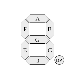
Figure 2: 7-Segment Display with labeled segments (a, b, c, d, e, f, g) showing the complete interface system. Reference: Theory section
Components Required
- 1 BCD to 7-Segment Decoder (pre-loaded)
- 1 7-Segment Display unit (pre-loaded)
- Input connections for A, B, C, D
Circuit Connections
- The circuit board contains pre-loaded components: Input bits (A, B, C, D), BCD to 7-segment Decoder, and 7-segment Display.
- Connect the input bits A, B, C, D to the corresponding inputs of the BCD decoder by dragging your cursor from one endpoint to another.
- Connect the decoder outputs (a, b, c, d, e, f, g) to the corresponding inputs of the 7-segment display:
- Connect decoder output 'a' to display input 'a'
- Connect decoder output 'b' to display input 'b'
- Continue this pattern for all seven segments (c, d, e, f, g)
- Set the input values for A, B, C, D by double-clicking on the input bits to test different BCD combinations.
- Click on "Simulate" to activate the display and observe the digit representation.
Truth Table for BCD to 7-Segment Decoder
| A | B | C | D | Digit | a | b | c | d | e | f | g |
|---|---|---|---|---|---|---|---|---|---|---|---|
| 0 | 0 | 0 | 0 | 0 | 1 | 1 | 1 | 1 | 1 | 1 | 0 |
| 0 | 0 | 0 | 1 | 1 | 0 | 1 | 1 | 0 | 0 | 0 | 0 |
| 0 | 0 | 1 | 0 | 2 | 1 | 1 | 0 | 1 | 1 | 0 | 1 |
| 0 | 0 | 1 | 1 | 3 | 1 | 1 | 1 | 1 | 0 | 0 | 1 |
| 0 | 1 | 0 | 0 | 4 | 0 | 1 | 1 | 0 | 0 | 1 | 1 |
| 0 | 1 | 0 | 1 | 5 | 1 | 0 | 1 | 1 | 0 | 1 | 1 |
| 0 | 1 | 1 | 0 | 6 | 1 | 0 | 1 | 1 | 1 | 1 | 1 |
| 0 | 1 | 1 | 1 | 7 | 1 | 1 | 1 | 0 | 0 | 0 | 0 |
| 1 | 0 | 0 | 0 | 8 | 1 | 1 | 1 | 1 | 1 | 1 | 1 |
| 1 | 0 | 0 | 1 | 9 | 1 | 1 | 1 | 1 | 0 | 1 | 1 |
Observations
- The 7-segment display shows the corresponding decimal digit (0-9) for each valid BCD input combination (0000-1001).
- The display segments light up according to the truth table above, creating recognizable digit patterns.
- Invalid BCD inputs (1010-1111) may produce undefined patterns on the display.
- If the connections have been made correctly as described above, a "Success" message will be displayed upon clicking "Submit".
General Instructions
Navigation Between Tasks
- Use the task tabs at the top to switch between "Decoder" and "7-segment Display" tasks.
- Each task has specific components and objectives tailored to the learning goals.
- The observations section will be cleared when switching between tasks to avoid confusion.
Circuit Building Guidelines
- Components: Click on logic gates in the Components panel to add them to the circuit board.
- Movement: Drag and drop components to position them appropriately on the circuit board.
- Connections: Create wire connections by dragging from one endpoint to another.
- Input Values: Double-click on input bits to toggle between 0 and 1 values.
- Wire Deletion: Right-click on wire connections and select delete to remove unwanted connections.
- Component Deletion: Right-click on components and select delete to remove them from the circuit.
Testing and Validation
- Simulate: Click the "Simulate" button to test your circuit with the current input values.
- Submit: Click the "Submit" button to validate your complete circuit implementation.
- Reset: Use the "Reset" button to clear the circuit board and start over.
- Multiple Tests: Try different input combinations to verify your circuit works for all valid BCD inputs (0-9).