
Zener Diode as Voltage Regulator
Apparatus
Zener diode, resistor, variable DC power supply, milliammeter, voltmeter, Rheostat and wire.
Controls
Insert Key Button: This is used to insert key on the switch connected with the battery. This key is only activated when the connection is perfect.
Choose Zener Diode: This combo box is used to select different zener diodes having different zener voltages.
Series Resistance: Value of the Series Resistance can be directly input here.
Slider
Rheostat Value: Rheostat can be controlled by using this slider.
Load Resistance: Value of load resistance can be set or changed by using this slider.
Button
Reset Button: To reset all the connections.
Procedure
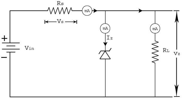
Using the circuit diagram, identify the connections in the given platform. Connections are made as shown in the below diagram.
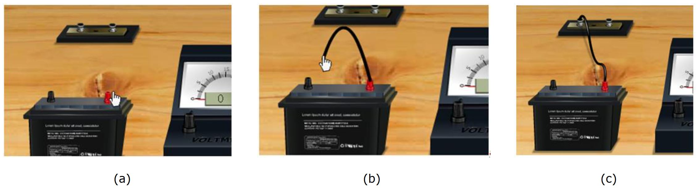
How to make connections in simulation ?
Click one end node of the battery and drag to the next position, where we want to connect the wire. Just like shown in the figures below:
Full connection diagram
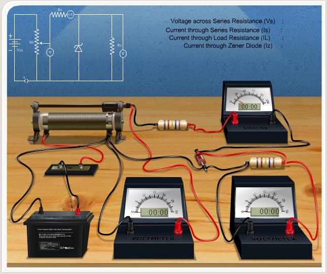
If the connections are correct, Insert Key option activated.
Line Regulation
- Choose the zener diode to start the experiment.
- Insert the series resistance value.
- Fix the load resistance value by using the $Load Resistance slider.
- Change the Rheostat value from maximum to 0 in intervals of 100.
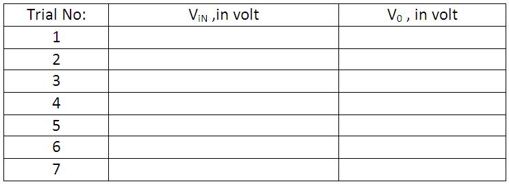
- Note down the corresponding input voltage and output voltage, and tabulate it.
- Plot the graph with on the x-axis and on the y-axis.
Percentage of Line regulation =
Load Regulation
- First 3 steps are the same as above.
- Fix the Rheostat value to get 12 V at the voltmeter across the rheostat.
- Change the Load Resistance in intervals of 100 Ω / 1000 Ω up to the maximum range.
- Note the readings and tabulate them.
- Plot the graph with on the x-axis and on the y-axis.
Let us consider is the output voltage when there is no load resistance (ideally VNL = Zener voltage) and is the output voltage when load resistance is maximum.
Percentage of Load regulation =
Note: This is an ideal circuit. For a real circuit, there will be small variations in output voltage with varying input voltage or load resistance.