
Zener Diode-Voltage Regulator 
Procedure
Zener Diode - Line Regulation
- Set the Zener Voltage(VZ)
- Set the Series Resistance (RS) value.
- Set the Load Resistance (RL) value.
- Vary DC voltage.
- Voltmeter is placed parallel to load resistor and ammeter series with the series resistor.
- Choose appropriate DC voltage such that zener diode is 'on'.
- Now note the Voltmeter and Ammeter reading for various DC voltage.
- Note the Load current(IL), zener current(IZ), Output voltage(VO)
- Calculate the voltage regulation.
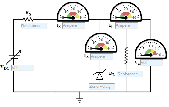
Figure:1
Zener Diode - Load Regulation
- Set DC voltage.
- Set the Series Resistance (RS) value.
- 1W D0-41 Glass Zener Diode 1N4740A, Zener voltage is 10 V.
- Vary the Load Resistance (RL).
- Voltmeter is placed parallel to load resistor and ammeter series with the series resistor.
- Choose Load Resistance in such a manner, such that the Zener diode is 'on'.
- Now note the Voltmeter and Ammeter reading for various Load Resistance.
- Increase the load resistance (RL).
- Note the Load current (IL), zener current (IZ), Output voltage(VO)
- Calculate the voltage regulation.
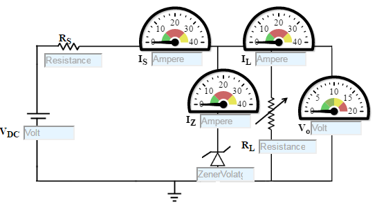
Figure: 2
Zener Characteristics
- Select the diode
- Set the rheostat Rh=1 Ω
- By adjusting the rheostat, voltmeter reading is increased from 0 and in each time note the corresponding reading in milliammeter.
- Take the readings and note Voltmeter reading across Zener diode and Ammeter reading.
- Plot the V-I graph and observe the change.
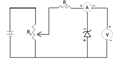
Figure: 3