Universal Joint
Objective
After completing the simulation experiments on balancing of multiple masses in single plane one should be able to
- To understand the relative motion between the output and the input shaft of the universal joint.
- To understand the variation of angle output shaft and input shaft.
Introduction:
A universal joint is a joint or coupling in a rigid rod that allows the rod to 'bend' in any direction and is commonly used in shafts that transmit rotary motion. It consists of a pair of hinges located close together, oriented at 90° to each other, connected by a cross shaft. It is not a constant velocity joint. The universal joint suffers from one major problem: even when the input drive shaft axle rotates at a constant speed, the output drive shaft axle rotates at a variable speed, thus causing vibration and wear.
You can understand the parts of a universal coupling clearly by taking a look at the exploded view shown below. To know more about the parts.
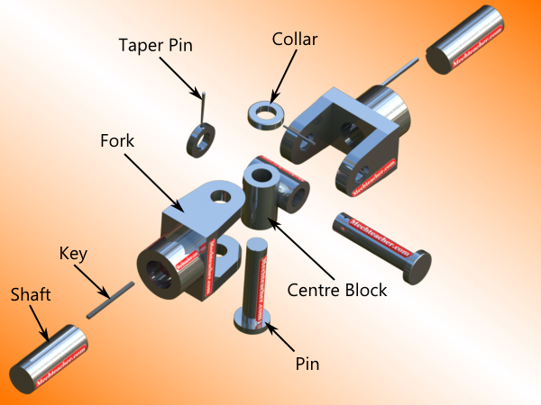
Fig: Exploded view of a Universal Joint
The two fork ends are assembled co-axially with respect to the centre block. The pins are assembled into the holes provided in the fork end. They are held in position by means of a collar and a collar pin. The assembled view of a universal joint is shown below. For a detailed understanding of the assembly of a typical universal joint. Impact testing machine consists of a pendulum suspended from a short shaft that rotates in ball bearing and swings midway between two rigid upright stands supported on a rigid base near the bottom of which are the specimen supports anvils. The knife-edge or striking edge is slightly rounded. The pendulum can be raised to any desired height and rested at that position. It is supported in the starting position by a catch and can be released by a trigger. The mechanism is so designed that the pendulum is not disturbed when the catch is released.
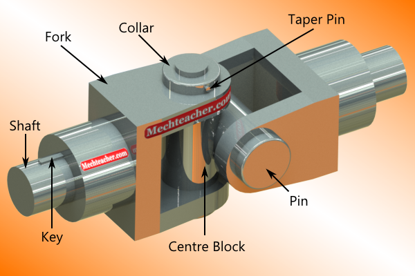
Fig: Assembled View
Universal joint has a wide range of applications. It is used in:
- Driveshafts
- Automobile propeller shafts
- Stone crushers
- Tapping machinery
- Centrifugal blowers
- Centrifugal fans and centrifugal pumps
- Belt conveyors
- Control mechanisms
- Marine equipment
- Metal forming machinery
- Sockets
The figure given below showing in the car universal joint connected to propeller shaft for transmitting the power.

Fig: Universal joint in the car
MATHEMATICAL EQUATIONS
The variation in the speed of the driven shaft depends on the configuration of the joint, which is specified by three variables:

 = The angle of rotation for axle 1
 = The angle of rotation for axle 2
 = The bend angle of the joint
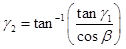
The angular position of the rotation axle 2 is given by:
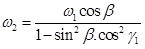
The angular velocity of the rotation axle 2 is given by: