
Three Phase Voltage Source Inverter with SPWM
Introduction
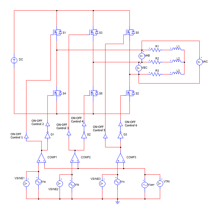
A three-phase Voltage Source Inverter (VSI) with SPWM (Sinusoidal Pulse Width Modulation) is a type of inverter that converts DC voltage into three-phase AC voltage with sinusoidal waveforms. It works by varying the pulse width of a high-frequency carrier signal according to the instantaneous amplitude of a reference sinusoidal waveform. In a 3-phase inverter, three separate SPWM signals are generated for each phase, By comparing a high-frequency triangular waveform with three sinusoidal reference waveforms (one for each phase) to determine the pulse widths of the inverter's switching devices.
It is widely used in various applications, including motor drives, renewable energy systems, and grid-tied applications. The SPWM technique ensures that the output voltage closely follows the shape of the desired sinusoidal waveform.
Sinusoidal Pulse Width Modulation Technique
A three-phase VSI consists of six power semiconductor switches, typically insulated-gate bipolar transistors
(IGBTs) or power MOSFETs, arranged in an H-bridge configuration.
The switches are grouped into three pairs, each controlling one phase of the output voltage (Va, Vb, and
Vc). To generate the desired three-phase sinusoidal output, three reference sinusoidal waveforms (Vra, Vrb, and
Vrc) are generated. These reference waveforms have a fixed frequency (ω) and amplitude (Vm) and are phase-shifted by 120 degrees
relative to each other.
The reference waveform for each phase is given by:
Vra(t) = Vm * sin(ωt)
Vrb(t) = Vm * sin(ωt - 2π/3)
Vrc(t) = Vm * sin(ωt + 2π/3)
A high-frequency triangular carrier waveform (Vcarr) is generated with a frequency (fc) much higher than the
desired output frequency of the inverter. The carrier waveform varies between -Vc and +Vc, where Vc is the peak amplitude of the carrier waveform.
The instantaneous values of the reference sinusoidal waveforms (Vra, Vrb, and Vrc) are continuously compared
with the triangular carrier waveform (Vcarr) using comparators.
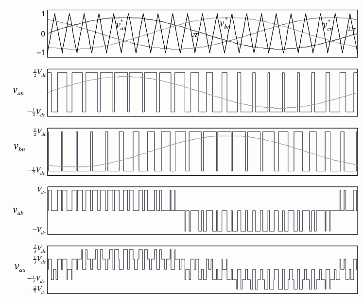
Based on the comparison, the inverter switches are turned ON or OFF for specific durations, determining the
pulse width of the output voltage. When the reference waveform is greater than the carrier waveform,
the corresponding switch is turned ON. When the reference waveform is smaller, the switch is turned OFF,
during the positive half-cycle of the reference waveform Vra(t), the switch S1 (top switch) and S4 (bottom
switch) for phase A are turned ON if Vra(t) > Vcarr(t).
The switches will remain ON until Vra(t) < Vcarr(t) during the negative half-cycle.
The same process is applied to the other phases, with switches S2, S5, S3, and S6 for phases B and C,
respectively.
In this PWM based on comparison with the triangular wave, if the ratio of carrier frequency to fundamental
frequency is large enough (greater than 21), then the fundamental component of the output voltage varies linearly with the reference voltage vref for a constant DC-link voltage as
$v_{o1} = v_{ref} ; sin ; w t..........(1)$
The output voltage can be rewritten in terms of the modulation index MI as
$v_{o1} = \frac {v_{dc}} {2} ;MI ;sin ;wt..........(2)$
Modulation index (MI): It determines the extent to which the reference waveforms are compared with the carrier waveform. It influences the amplitude of the output voltage. The modulation index is given by:
$MI = \frac {V_m}{V_c}..........(3)$
The SPWM technique allows the 3-phase VSI to generate a smooth and accurate sinusoidal output voltage, which is crucial in applications where a clean and stable AC supply is required. The modulation index (MI) can be adjusted to control the output voltage amplitude, and the carrier frequency (fc) can be selected to optimize efficiency and harmonic performance.
The range of 0 < MI < 1 is called the linear modulation range because, in this range, the inverter can
generate an output voltage linearly proportional to the reference voltage. In this case, the PWM
inverter is considered to be simply a voltage amplifier with a unit gain.
However, when the reference exceeds the peak of the triangular carrier (i.e.,
MI > 1), the inverter cannot produce an output voltage linearly proportional to the
voltage reference. The range of MI > 1 is called overmodulation region, where
the linearity of the modulation is lost.
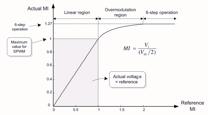
The maximum linear output voltage, Vdc/2, attainable by the SPWM technique corresponds to 78.5% of the maximum output voltage, 2Vdc/π, by the six step inverter. Therefore, when using the PWM technique, the attainable maximum limit of the linear modulation range is inevitably less than the maximum output voltage of an inverter.
Advantages of Three Phase Voltage Source Inverter with SPWM
High-quality output waveform: SPWM inverters can produce high-quality sinusoidal output waveforms with low harmonic distortion. This is crucial in applications where a clean and stable AC supply is required, such as in motor drives, induction heating, renewable energy systems, and grid-tied inverters.
Better motor control: SPWM inverters are commonly used in motor drives, where precise control of the motor's speed and torque is essential. The smooth and accurate sinusoidal output waveform of SPWM inverters leads to improved motor performance and reduced torque ripple.
Flexibility in voltage and frequency control: SPWM inverters allow for easy control of output voltage and frequency. By adjusting the modulation index and carrier frequency, the output voltage and frequency can be varied to meet the requirements of different loads.
Reduced output filter requirements: The high-quality sinusoidal output waveform of SPWM inverters results in lower harmonic content, reducing the need for complex and bulky output filters, which can help save cost and space in the system.
Disadvantages of Three Phase Voltage Source Inverter with SPWM
High switching losses: SPWM inverters operate at high switching frequencies to achieve smooth output waveforms. However, the increased switching frequency can lead to higher switching losses in the power devices (transistors or IGBTs), reducing overall efficiency. Careful design and the use of advanced switching devices can help mitigate this issue.
Complex control circuitry: The implementation of SPWM requires sophisticated control circuitry to compare reference waveforms with the carrier waveform accurately. The complexity of the control circuit can increase the overall cost and complexity of the inverter system.
Sensitivity to parameter variations: SPWM inverters performance can be sensitive to changes in the circuit parameters, load conditions, and temperature. Maintaining accurate and stable control under arying conditions may require sophisticated control algorithms and compensation techniques.
Cooling requirements: The high switching frequencies and power levels involved in SPWM inverters may require effective cooling solutions to dissipate heat from power devices and associated components.
Applications of Three Phase Voltage Source Inverter with SPWM
Motor Drives: SPWM inverters are extensively used in motor drives for controlling the speed and torque of AC induction motors or permanent magnet synchronous motors (PMSMs). The smooth and accurate sinusoidal output waveform of SPWM ensures efficient and reliable motor operation with reduced harmonic losses and minimal torque ripple.
Renewable Energy Systems: In renewable energy systems, such as solar inverters and wind turbine converters, SPWM inverters are utilized to convert the DC output of solar panels or wind turbines into clean and stable AC power. The high-quality output waveform is essential for efficient energy conversion and grid integration.
Power Conditioning: SPWM inverters can be used in power conditioning applications to improve power quality by compensating for voltage fluctuations, harmonics, and reactive power.
Aerospace and Defense: SPWM inverters are used in aerospace and defense applications, including aircraft power systems and military equipment, where precise control of AC voltage is necessary for avionics and electronics.