
Three Phase VSI with 120° and 180° Conduction Mode
Introduction
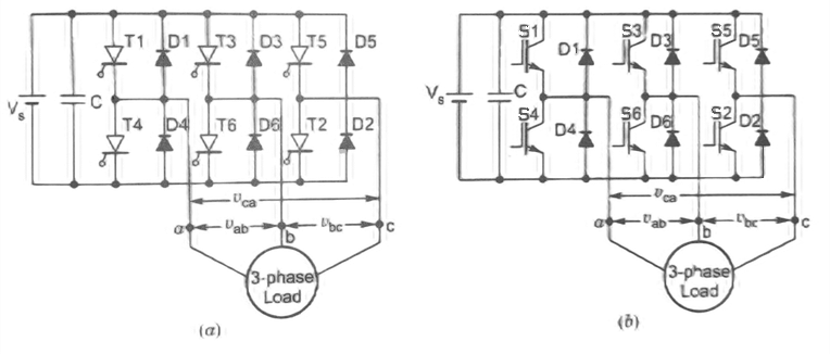
A three-phase inverter is a type of power electronic device that converts DC (Direct Current) power into AC (Alternating Current) power with three phases. It is widely used in various applications such as motor drives, renewable energy systems, and power transmission. The main function of a three-phase inverter is to control the switching of power electronic devices, typically transistors or IGBTs (Insulated Gate Bipolar Transistors), to generate three-phase AC output voltage. The three-phase inverter consists of six switches, typically arranged in a bridge configuration, and each phase is connected to a load as shown in Figure 1. The switching patterns and timing of the switches determine the shape, magnitude, and frequency of the output voltage.
1. Three Phase 180° Mode Voltage Source Inverter
In this conduction mode of three phase inverter, each thyristor conducts for 180°. Thyristor pair in each arm i.e. (T1, T4), (T3, T6) and (T5, T2) are turned on with a time interval of 180°.
It means that T1 remains on for 180° and T4 conducts for the next 180° of a cycle. Thyristors in the upper group i.e., (T1, T3 & T5) conducts at an interval of 120°.
It implies that if T1 is fired at ωt = 0° then T3 will be fired at 120° and T5 at 240°. Same is also true for lower group thyristors i.e., (T4, T6 & T2).
On the basis of the above mentioned firing scheme, Below is a figure showing the conduction periods of various thyristors in a three-phase inverter.
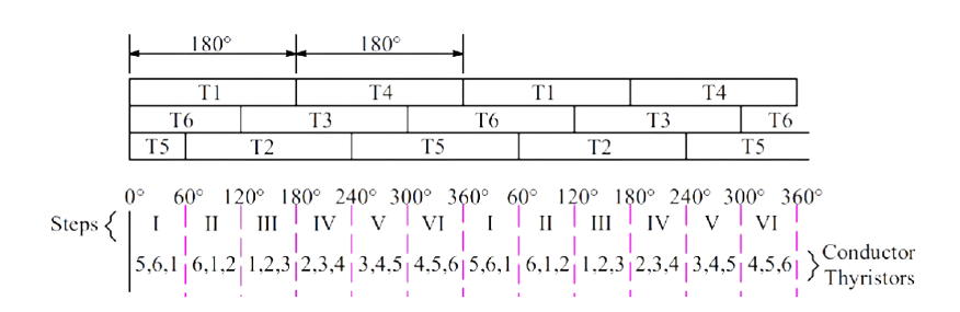
As we observe from the first row of the above table that T1 conducts for 180° while T4 conducts for next 180° and then again T1 for 180° and so on. In the second row, T3 from the upper group is shown conducting 120° after T1 starts conducting. After T3 conducting for 180°, T6 conducts for the next 180° and again T3 for next 180° and so on. Further, in the third row, T5 from the upper group starts conducting 120° after T3 or 240° after T1. After T5 conduction for 180°, T2 conducts for next 180°, T5 for the next 180° and so on. In this way, the pattern for firing of thyristors are identified.
From the above table, the six steps for firing of thyristors may be formulated. As you can see from the table that, the overlapping period of the three SCRs are only 60°, this is the reason, it is said that each step for a three phase bridge inverter is 60°. Let us now try to define the steps.
During Step-I, SCRs 5, 6 & 1 are conducting. These are shown as closed switches and the non-conducting SCRs are shown as open switches.
The load terminals a & c are connected to the positive bus of DC source whereas terminal b is connected to the negative bus of DC source.
The load voltage Vab = Vbc = Vs in magnitude. The magnitude of neutral voltage can be calculated as shown below:
During step-I, 0 ≤ ωt < π/3, only 5, 6, and 1 thyristors are conducting.
Current,
$$i_1 = \frac {V_s} {\left(Z+ \frac{Z}{2}\right)} = \frac {2}{3} . \frac {V_s}{3}$$
the line to neutral voltages are
$$v_{ao} = v_{co} = i_1 \frac {Z}{2} = \frac {V_s}{3}$$
$$v_{bo} = i_1 Z = 2\frac {V_s}{3}$$
The above line to neutral voltage may be written as
$$V_{ao} = V_{co}= \frac {V_s}{3}$$
$$V_{bo} = -\left(2\frac {V_s}{3}\right)$$
During step-II, π/3 ≤ ωt < 2π/3, only 6, 1, and 2 thyristors are conducting.
Current,
$$i_2 = \frac {2}{3} \frac{V_s}{Z}$$
So,
$$v_{ao} = i_2 Z = 2\frac {V_s}{3}; v_{bo} = v_{co} = i_2 \frac {Z}{2} = \frac {V_s}{3}$$
$$v_{ao} = 2\frac {V_s}{3} , v_{bo} = v_{co} = - \frac {V_s}{3}$$
The output voltages as calculated for step-I & II are plotted to get the output voltage waveform of the three phase bridge inverter. The variation in phase voltages for remaining steps are calculated in the same manner and plotted. The output voltage waveform is shown below.
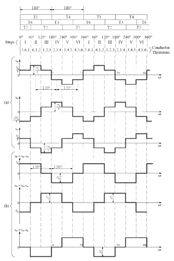
From the above waveform, it is clear that for each cycle of output voltage of each phase, six steps are required and each step has a duration of 60°. The line voltage Vab = Vao + Vbo or Vsb = Vao – Vbo is obtained by reversing Vbo and adding it to Vao. This is shown in the output waveform (b). Similarly, line voltages Vbc & Vca are plotted.
Formula of Line and Phase Voltage: The Fourier analysis of output voltage can be described by the Fourier series as follows
$$v_{ab} = \Sigma_{n=1, 3, 5...}^ \infty \frac {4V_s}{n \pi} cos \left(\frac {n \pi}{6}\right) sin ~ n\left(\omega t + \frac {\pi} {6}\right)....(1)$$
Similarly,
$$v_{bc} = \Sigma_{n=1, 3, 5...}^ \infty \frac {4V_s}{n \pi} cos \left(\frac {n \pi}{6}\right) sin ~ n\left(\omega t - \frac {\pi} {2}\right)....(2)$$
$$v_{ca} = \Sigma_{n=1, 3, 5...}^ \infty \frac {4V_s}{n \pi} cos \left(\frac {n \pi}{2}\right) sin ~ n\left(\omega t + \frac {5\pi} {6}\right)....(3)$$
RMS value of nth component of line voltage is
$$V_{Ln} = \frac {4V_s}{ \sqrt 2 n \pi}. cos \left(\frac {n \pi}{6}\right)....(4)$$
RMS value of fundamental line voltage is
$$V_{L1} =\frac {4V_s}{ \sqrt 2 \pi} . cos \left(\frac {\pi}{6}\right) = 0.7797 V_s....(5)$$
RMS value of line voltage is given by
$$V_L = \bigg[\frac {1}{\pi} \int _0^{\frac{2 \pi}{3}} V_s^2 . d( \omega t)\bigg]^{1/2} = 0.8165 V_s....(6)$$
RMS value of phase voltage is
$$V_{p} = \frac {V_L}{ \sqrt 3} = \frac { \sqrt 2}{3} V_s = 0.4714 V_s....(7)$$
RMS value of fundamental phase voltage is
$$V_{p1} = \frac {2V_s}{\sqrt 2 \pi} = 0.4502 V_s....(8)$$
Advantages of Three-Phase 180° Conduction Mode Inverter
Higher fundamental output voltage: The 180° conduction mode results in a higher fundamental output voltage compared to the 120° mode, which can be beneficial for applications requiring higher output voltage levels.
Lower voltage stress: The devices experience lower voltage stress during each switching cycle compared to the 120° mode, potentially reducing the voltage rating requirements for the devices.
Compatibility with High-Voltage Applications: The 180° conduction mode inverter is well-suited for high-voltage applications where a higher output voltage is required. It can be used in power transmission and distribution systems, high-voltage motor drives, and grid-tied systems, among others.
Disadvantages of Three-Phase 180° Conduction Mode Inverter
Higher harmonic content: The 180° conduction mode may introduce higher harmonic distortion in the output waveform compared to the 120° mode, which may require additional filtering or compensation techniques.
Increased switching losses: Since the devices are switched on for a longer duration, there are increased switching losses, which can reduce the overall efficiency of the inverter.
Complex Control Requirements: The 180° conduction mode inverter typically requires more complex control algorithms and strategies compared to the 120° mode. The extended conduction angle necessitates precise control of the switching devices to maintain the desired output voltage and minimize harmonic distortion.
Applications of Three-Phase 180° Conduction Mode Inverter
High Voltage Applications: The 180° conduction mode inverter is suitable for applications that require higher output voltage levels, such as high-voltage motor drives, electrochemical processes, or certain types of industrial equipment. The higher fundamental output voltage can meet the specific voltage requirements of these applications.
Power Transmission and Distribution: In certain cases, a 180° conduction mode inverter can be used in high-voltage DC (HVDC) systems for long-distance power transmission. It allows for efficient conversion between AC and DC power with reduced switching losses.
Grid-Tied Systems: In grid-tied applications where the inverter is connected to the utility grid, a 180° conduction mode inverter may be used. Grid-connected inverters typically require a higher fundamental output voltage to synchronize with the grid voltage and inject power into the utility network.
2. Three Phase 120° Mode Voltage Source Inverter
In this conduction mode inverter, each thyristor conducts for 120° of a cycle. Like 180° mode, 120° mode inverter also requires six steps, each of 60° duration, for completing one cycle of the output AC voltage. Here it should be noted that step is nothing but the change in firing of one thyristor to the next thyristor in a proper sequence.The firing sequence for 120° Mode Inverter Operation is tabulated below.
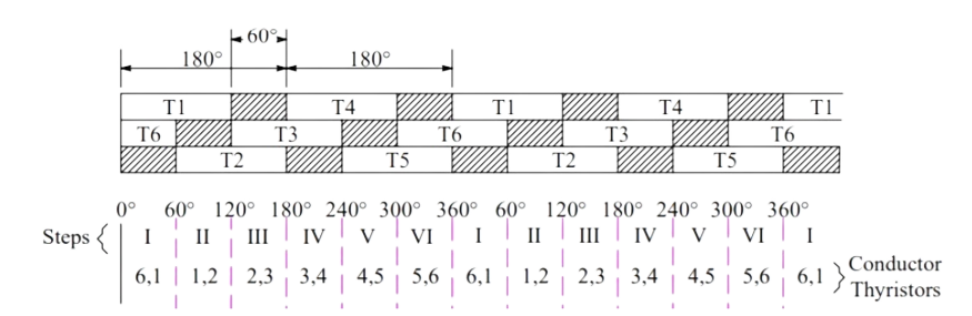
It can be seen from the above table that each of the thyristor conducts for 120° duration only and it remains off for the next 60°.
This is different from 180° operation mode where each thyristor conducts for 180° duration,
In the first row of table, T1 is shown to be conducting for 120° and for the next 60° neither T1 nor T4 conducts. T4 is turned ON at ωt = 180° and it further conducts for next 120° i.e., upto ωt = 300°.
This simply means that for 60° interval i.e., from ωt = 300° to 360°, neither T1 nor T4 conducts. In fact, at ωt = 300°, T4 is tuned OFF and at ωt = 360°, T1 is turned ON again.
In the second row of table, T3 is turned ON at ωt = 120° and it conducts for next 120°. Then 60° interval elapses during which neither T3 nor T6 conducts. At ωt = 300°, T6 is turned ON. It also conducts for next 120° and then 60° interval elapses after which T3 is turned ON again. The third row is also completed in the same manner, The table for firing sequence can be used to define the steps of the three phase inverter for its 120° mode operation. In Step-I, T1 & T6 should be gated, T1 & T2 for step-II, T2 & T3 for step-III and so on. During each step, only two thyristors are conducting - one from the upper arm and another one from the lower arm.
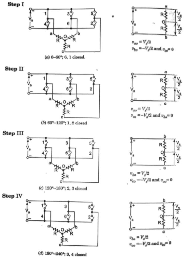
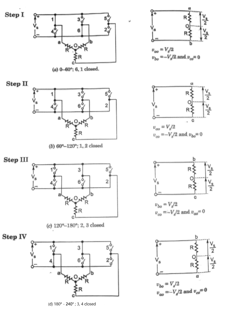
The circuit models for steps I-IV are shown in the Fig. 6, where load is assumed to be resistive and star connected. During step I, thyristor 6, 1 are conducting and
and as such load terminal a is connected to positive bus of dc source whereas terminal b is connected to negative bus od dc source. Load terminal c is not connected to dc bus. The line to neutral voltage are
$$v_{ao} = \frac {V_s}{2}, v_{ob} = \frac {V_s}{2}$$
or
$$v_{bo} = \frac {-V_s}{2}$$
and
$$v_{co} = 0$$
For step II, thyristor 1, 2 conduct and load terminal a is connected to positive bus of dc source whereas terminal c is connected to negative bus od dc source. Load terminal b is not connected to dc bus. The line to neutral voltage are
$$v_{ao} = \frac {V_s}{2}$$
or
$$v_{co} = -\frac {V_s}{2}$$
and
$$v_{bo} = 0$$
This procedure is followed to obtain load voltage for the remaning steps and these phase voltage are plotted in Fig. 7
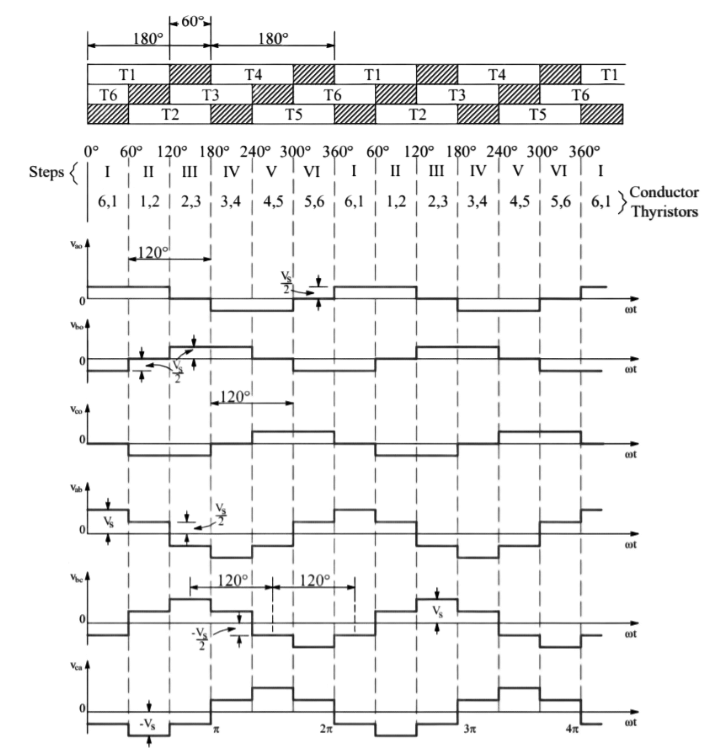
Formula of Line and Phase Voltage:
The Fourier analysis of phase voltage waveform vao is
$$v_{ao} = \Sigma_{n=1, 3, 5...}^ \infty \frac {2V_s}{n \pi} cos \left(\frac {n \pi}{6}\right) sin ~ n\left(\omega t + \frac {\pi} {6}\right)....(9)$$
Similarly,
$$v_{bo} = \Sigma_{n=1, 3, 5...}^ \infty \frac {2V_s}{n \pi} cos \left(\frac {n \pi}{6}\right) sin ~ n\left(\omega t - \frac {\pi} {2}\right)....(10)$$
$$v_{co} = \Sigma_{n=1, 3, 5...}^ \infty \frac {2V_s}{n \pi} cos \left(\frac {n \pi}{5}\right) sin ~ n\left(\omega t + \frac {5\pi} {6}\right)....(11)$$
The Fourier analysis of line voltage waveform vab is
$$V_{ab} = \Sigma_{n=6k \pm 1}^\infty \frac {3V_s}{n \pi}. sin ~ n \left(\omega t + \frac {\pi}{3}\right) ....(12)$$
where k = 0, 1, 2,....
Similar expressions for vbc and vca can also be written.
RMS Value of fundamental phase voltage is
$$V_{p1} = \frac {2V_s}{\sqrt 2 \pi} . cos \left(\frac {\pi}{6}\right) = 0.3898 V_s....(13)$$
RMS value of phase voltage is
$$V_p = \bigg[ \frac {1}{ \pi} \int_0^{\frac {2 \pi}{3}} \bigg(\frac {V_s}{2}\bigg)^2 . d(\omega t) \bigg]^{1/2} = 0.4082 V_s....(14)$$
RMS value of fundamental line voltage is
$$V_{L1} = \frac {3V_s}{ \sqrt 2 \pi } = 0.6752 V_s = \sqrt 3 V_{p1}....(15)$$
RMS value of line voltage is
$$V_L = \sqrt 3 V_p = \frac {V_s}{\sqrt 2} = 0.7071 V_s....(16)$$
Comparison of 180° and 120° conduction schemes: For 180° conduction scheme, there is no delay between switching on and switching off of the switches in the same arm. Moreover, in this case, switches of same leg turn-on and turn-off alternately (e.g., T1 and T4 for leg of phase A). Thus, a blanking or idle period is provided between switching of both switches, otherwise the overlapping of conduction period of these switches may short circuit the input DC source. This problem is overcome in 120° conduction scheme, where a gap of 60° or appears between turn on and turn off of two switches of same leg. This results in reliable and safe operation of the inverter, at the cost of poor utilization of the switches capacity.
Advantages of Three-Phase 120° Conduction Mode Inverter
Lower harmonic content: The 120° conduction mode helps reduce the harmonic distortion in the output waveform, resulting in a cleaner power output.
Reduced switching losses: Since the devices are only switched on for a shorter duration, there is lower switching loss and improved overall efficiency.
Compatibility with Motor Drives: The 120° conduction mode inverter is commonly used in motor drives, including induction motors and synchronous motors. The lower harmonic content and improved efficiency make it suitable for applications that require precise motor control, reduced electrical noise, and improved motor performance.
Disadvantages of Three-Phase 120° Conduction Mode Inverter
Higher voltage stress: The devices experience higher voltage stress during each switching cycle due to the shorter conduction angle, which may require higher voltage ratings for the devices.
Lower fundamental output voltage: The output voltage waveform of a 120° conduction mode inverter has a lower fundamental voltage compared to the 180° conduction mode, which may impact certain applications.
Applications of Three-Phase 120° Conduction Mode Inverter
Motor Drives: Inverter-fed induction motors and synchronous motors can be controlled using a 120° conduction mode inverter. The lower harmonic content and improved efficiency make it suitable for applications that require precise motor control and reduced electrical noise.
Renewable Energy Systems: Three-phase inverters used in solar photovoltaic (PV) systems or wind energy systems often employ the 120° conduction mode. The reduced harmonic distortion and higher efficiency are important for converting the DC power generated by the renewable sources into clean and stable AC power for the grid or local consumption.
UPS Systems: Uninterruptible Power Supply (UPS) systems often utilize 120° conduction mode inverters to provide backup power during outages. The lower harmonic content helps to maintain the quality of the output power and reduce potential disturbances to connected equipment.