
Three Phase Full Wave Silicon Controlled Rectifier with R Load, RL Load & RLE Load
Introduction
A controlled rectifier is an electronic circuit that converts alternating current (AC) into direct current
(DC). It consists of power electronic devices, typically thyristors or silicon-controlled rectifiers (SCRs),
which are controlled to switch the flow of current in a desired manner.
The main function of a controlled rectifier is to control the magnitude and polarity of the output DC voltage.
It is commonly used in various applications where precise control over the rectification process is required
such as power supplies, motor drives, battery chargers, and voltage regulators.
The controlled rectifier operates by using a triggering mechanism to turn on the thyristors at specific points
in the AC waveform. Once the thyristors are triggered, they conduct current until the AC voltage crosses zero
or until the thyristor is turned off. By controlling the timing of thyristor firing, the rectifier can vary
the average DC output voltage.
Three Phase Full Wave Controlled Bridge Rectifier
A three-phase full-wave controlled rectifier, also known as a three-phase thyristor rectifier or six-pulse
rectifier, is a type of rectifier circuit used to convert alternating current (AC) into direct current (DC).
It utilizes six thyristors (also known as silicon-controlled rectifiers or SCR) to control the flow of
current. Here's how a three-phase controlled rectifier works:
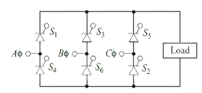
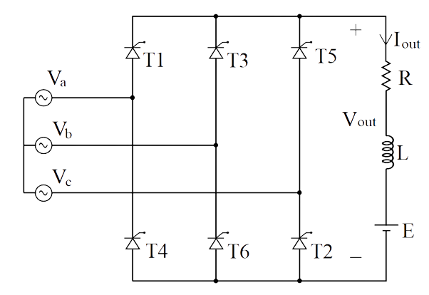
- Kirchhoff’s voltage law around any path shows that only one thyristor in the
top half of the bridge may conduct at one time (S1, S3, or S5). The thyristor that is conducting will have its anode connected to the phase voltage that is highest at that instant.
- Kirchhoff’s voltage law also shows that only one thyristor in the bottom half of
the bridge may conduct at one time (S2, S4, or S6). The thyristor that is
conducting will have its cathode connected to the phase voltage that is
lowest at that instant.
- As a consequence of points 1 and 2, S1 and S4 cannot conduct at the
same time. Similarly, S3 and S6 cannot conduct simultaneously, nor can S5
and S2.
- The output voltage across the load is one of the line-to-line voltages of the
source. For example, when S1 and S2 are on, the output voltage is Vac.
Furthermore, the thyristors that are on are determined by which line-to-line
voltage is the highest at that instant. For example, when Vac is the highest
line-to-line voltage, the output is Vac.
- There are six combinations of line-to-line voltages (three phases taken two
at a time). Considering one period of the source to be 360°, a transition of
the highest line-to-line voltage must take place every 360°/6 = 60°. Because
of the six transitions that occur for each period of the source voltage, the
circuit is called a six-pulse rectifier.
The three-phase full-wave controlled rectifier is widely used in applications that require variable DC voltage
and current, such as industrial motor drives, battery charging systems, and power supplies. By adjusting the
firing angle of the thyristors, the rectifier can control the output voltage and power delivered to the load,
enabling precise control of various electrical processes.
1. Three Phase Full Wave Controlled Rectifier - R Load
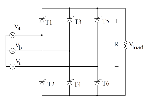
One thyristor of the conducting pair powers the positive side of load, while the other thyristor powers the
negative side of the load. Thyristors T1, T3, T2, and T4 form a
bridge rectifier network between phases A and
B, similary thyristors T3, T5, T4, and T6 between phases B and C
and T5, T1, T6, and T2 between phases C and A.
Thyristors T1, T3 and T5 feed the positive rail. The thyristor which has a
more positive voltage at its anode terminal
conducts. Likewise, thyristors T2, T4 and T6 feed the negative rail and
whichever thyristor has a more negative voltage
at its cathode terminal conducts.
Let,
$$V_{an} = V_{m} \ sinwt$$
$$V_{bn} = V_{m} \ sin \left(wt - \frac {2\pi}{3}\right)$$
$$V_{cn} = V_{m} \ sin \left(wt - \frac {4\pi}{3}\right)$$
$$V_{ab} = \sqrt 3 V_{m} \ sin \left(wt + \frac {\pi}{6}\right)$$
$$V_{bc} = \sqrt 3 V_{m} \ sin \left(wt - \frac {\pi}{2}\right)$$
$$V_{ca} = \sqrt 3 V_{m} \ sin \left(wt - \frac {7\pi}{6}\right)$$
The average of output voltage and current is,
$$V_{o} = \frac {3\sqrt 3}{\pi} V_{mp} \ cos\alpha .......(1)$$
$$I_{o} = \frac {3\sqrt 3}{\pi R} V_{mp} \ cos\alpha .......(2)$$
For α>60°
$$V_{o} = \frac {3}{\pi}\int_{\frac {\pi}{6} + \alpha}^{\frac {\pi}{2} + \alpha} \sqrt {3} V_{m} \ sin \bigg(wt + \frac {\pi}{6} \bigg) \ dwt = \frac {3\sqrt 3V_{m}}{\pi} cos \left(\frac {\pi}{3} + \alpha \right).......(3)$$
$$I_{o} = \frac {V_{dc}}{R} = \frac {3\sqrt {3}V_{m}}{\pi R} cos \left(\frac {\pi}{3} + \alpha \right).......(4)$$
2. Three Phase Full Wave Controlled Rectifier - RL Load
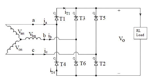
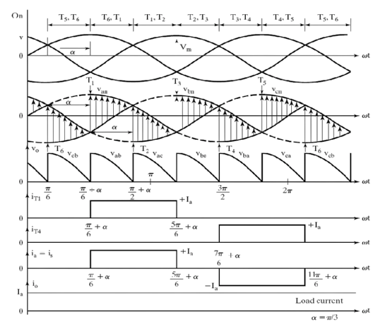
The thyristors are triggered at an interval of π/3 radians i.e., at an interval of 30°. The
frequency of output ripple voltage is 6 fs and the filtering requirement is less than that of three
phase semi and half wave converters.
At ωt = π/6 + α , thyristor T6 is already conducting when the T1 thyristor is turned
on by applying the
gating signal to the gate of T1. During the time period ωt = (π/6 +α) to (π/2 +α), thyristors
T1 and T6 conduct together and the line to line supply voltage vab appears across the
load.
At ωt = π/2 +α, the thyristor T2 is triggered and T6 is reverse biased immediately
and T6 turns
off due to natural commutation. The thyristors are numbered in the circuit diagram corresponding to the order
in which they are
triggered. The trigger sequence (firing sequence) of the thyristors is 12, 23, 34, 45, 56, 61, 12,
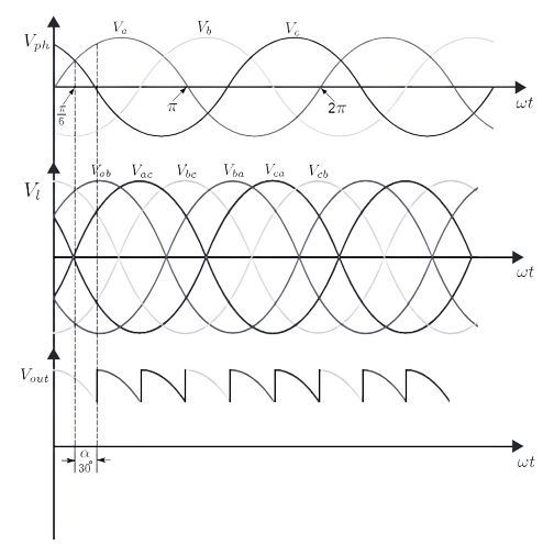
23, and so on. The figure shows the waveforms of three phase input supply voltages, output
voltage, the thyristor current through T1 and T4, the supply current through the line
'a'.
The average bridge output voltage is,
$$V_{o~(dc)} = V_{dc} = \frac {6}{2\pi} \int_{\frac {\pi}{6} + \alpha}^{\frac {\pi}{2} + \alpha} v_{o} \ d\omega t$$
$$v_{o} = v_{ab} = \sqrt {3} V_{m} \ sin \bigg(wt + \frac{\pi}{6} \bigg)$$
$$V_{dc} = \frac {3}{\pi} \int_{\frac {\pi}{6} + \alpha}^{\frac {\pi}{2} + \alpha} \sqrt {3} V_{m} \ sin \bigg(wt + \frac {\pi}{6} \bigg) d\omega t$$
$$V_{out} = \frac {3\sqrt {3}}{\pi} V_{mp} ~ cos \alpha .......(5)$$
The maximum average dc output voltage is obtained for a delay angle α = 0,
$$V_{dc~(max)} = V_{dm} = \frac {3\sqrt {3}}{\pi} V_{mp} .......(6)$$
The normalized average dc output voltage is
$$V_{dcn} = V_{n} = \frac {V_{dc}}{V_{dm}} = cos\alpha .......(7)$$
The rms value of bridge output voltage is,
$$V_{o~(rms)} = \left[\frac {6}{2\pi}\int_{\frac {\pi}{6} + \alpha}^{\frac {\pi}{2} + \alpha} V_{o}^2 ~ dwt\right]^{1/2}$$
$$V_{o~(rms)} = \left[\frac {6}{2\pi}\int_{\frac {\pi}{6}+\alpha}^{\frac {\pi}{2}+\alpha} V_{ab}^2 ~ dwt\right]^{1/2}$$
$$V_{o~(rms)} = \left[\frac {3}{2\pi}\int_{\frac {\pi}{6}+\alpha}^{\frac {\pi}{2}+\alpha} 3V_{m}^2 ~ sin^2 \left(wt + \frac {\pi}{6} dwt \right)\right]^{1/2}$$
$$V_{o~(rms)} = \left[\sqrt {3} V_{m} \left(\frac {1}{2} + \frac {3\sqrt {3}}{4\pi}cos2\alpha \right)\right]^{1/2}.......(8)$$
3. Three Phase Full Wave Controlled Rectifier - RLE Load
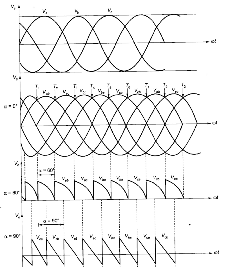
At α = 0°, T1 is triggered at ωt = π/6, T2 at 90°, T3 at 150° and so on. Therefore, Waveform of the load voltage shown in the figure. For α = 60°, the conduction sequence of thyristors T1 to T6 is shown in figure. Here T1 is triggered at ωt = 30° + 60° = 90°, T2 at 90° + 60° = 150° and so on. Each SCR conducts for 120°, when T1 is triggered, reverse biased thyristor T5 is turned off and T1 is turned on. T6 is already conducting. As T1 is connected to A and T6 to B, voltage vab appears across load. When T2 is turned on, T6 is commutated from the negative group. T1 is already conducting. As T1 and T2 are connected to A and C respectively, voltage vac appears across the load. Positive group of SCRs are fired at an interval of 120° and similary, negative group of SCRs are fired at an interval of 120°. But SCRs from both the groups are fired at an interval of 60°.
The average bridge output voltage is,
$$V_{out} = \frac {3\sqrt {3}}{\pi} V_{mp} ~ cos\alpha .......(9)$$
$$V_{out} = E + I_{out}\ R .......(10)$$
The Power delivered to load is,
$$P = EI_{out} + I_{r}^{2}R .......(11)$$
Advantages of Three Phase Full Wave SCR
A three-phase rectifier allows for higher power handling capability compared to single-phase rectifiers. It utilizes three phases of AC input, enabling the conversion of a larger amount of power.
The three-phase rectifier provides a smoother output compared to single-phase rectifiers. With three phases of AC input, the ripple content in the output DC waveform is significantly reduced, resulting in a more stable and constant DC voltage.
Due to the reduced ripple content, a three-phase rectifier has higher efficiency compared to single-phase rectifiers. The smoother output waveform leads to lower power losses and improved overall efficiency.
In a three-phase system, the load can be distributed more evenly among the three phases. This helps in maintaining balanced current and voltage levels, reducing stress on individual components and improving the system's overall reliability.
By controlling the switching of the rectifier devices, it is possible to reduce the harmonic distortion in the output waveform. This is particularly important in applications where harmonics can cause interference or damage to other sensitive equipment connected to the system.
The three-phase full-wave controlled rectifier provides flexibility in control and regulation of the output DC voltage. By adjusting the firing angles of the rectifier devices, the average output voltage can be controlled, allowing for precise regulation and adjustment of the DC power.
Many industrial and commercial applications utilize three-phase power systems. Using a three-phase rectifier ensures compatibility and seamless integration with these systems, making it a preferred choice in many applications.
Disadvantages of Three Phase Full Wave SCR
Compared to simpler rectifiers, a three-phase full-wave controlled rectifier requires more complex control circuitry to regulate the firing angles of the thyristors accurately. This complexity can increase the cost and complexity of the overall system.
The operation of the controlled rectifier introduces significant harmonic distortion in the output voltage and current waveforms. These harmonics can lead to undesirable effects such as increased losses, decreased power factor, and electromagnetic interference (EMI) issues. Additional filtering and power factor correction measures may be required to mitigate these effects.
Thyristors used in the controlled rectifier have relatively slow switching speeds compared to other power electronic devices like MOSFETs or IGBTs. This results in higher switching losses, leading to decreased overall efficiency of the rectifier.
Unlike other rectifier topologies, such as the active power factor correction (PFC) rectifier, a three-phase full-wave controlled rectifier has limited control over power factor correction. The power factor of the rectifier may be low, especially at light loads, which can cause additional energy losses and potential penalties from utility companies.
The thyristors in the controlled rectifier experience high voltage stress during commutation due to the rapid change in voltage across the device when it turns off. This stress can reduce the lifespan of the thyristors and require additional protection measures such as snubber circuits.
The output voltage of a three-phase full-wave controlled rectifier is typically determined by the input voltage and the modulation index (the ratio of the peak amplitude of the modulating signal to the peak amplitude of the carrier signal). This limited voltage control can be a disadvantage in applications where precise voltage regulation is required.
Applications of Three Phase Full Wave SCR
Variable Speed Drives
Uninterruptible Power Supplies (UPS)
HVDC Transmission Systems
Battery Charging Systems
Power Supplies for Electroplating