
Verification of Superposition and Thevenin's Theorem
Thevenin's Theorem and the Superposition Theorem are fundamental tools in linear electrical circuit analysis.
1. Thevenin's Theorem : Thevenin's theorem provides a method to simplify any complex linear circuit into a very simple equivalent circuit.
Statement:
• Any two-terminal, linear electrical network containing voltage sources, current sources, and resistors can be replaced by an equivalent circuit consisting of a single voltage source (Thevenin Voltage) in series with a single resistor (Thevenin Resistance).
• (Thevenin Voltage) is the open-circuit voltage measured across the two terminals.
• (Thevenin Resistance) is the equivalent resistance measured across the two terminals when all independent sources are turned off(i.e., independent voltage sources are replaced by short circuits, and independent current sources are replaced by open circuits).
• This equivalent circuit, known as the Thevenin equivalent circuit, is particularly useful when you need to analyze the behavior of the circuit across a changing load connected to the two terminals.
The circuit diagram shown below consists of a network connected to a load resistor RL.
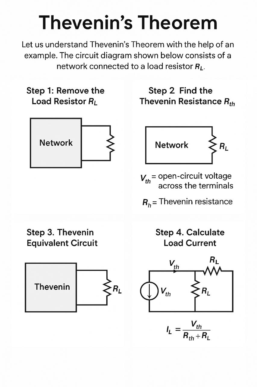
Step 1: Remove the Load Resistor RL
The open-circuit voltage across these terminals is known as Vth, calculated using standard circuit analysis techniques.
Step 2: Find the Thevenin Resistance Rth
Now deactivate all independent sources :
• Replace voltage sources with a short circuit.
• Replace current sources with an open circuit.
• Then, calculate the equivalent resistance across the open terminals. This resistance is called Rth.
Step 3: Thevenin Equivalent Circuit
Now construct the Thevenin equivalent circuit using the calculated values of Vth and Rth. Connect the load resistor RL back to this simplified circuit.
Step 4: Calculate Load Current
The load current IL flowing through RL can be calculated using Ohm’s Law:
Where:
Vth = Thevenin Voltage
Rth = Thevenin Resistance
RL = Load Resistance
Conclusion:
Thevenin’s Theorem allows you to simplify a complex circuit into a simple two-component equivalent, making analysis easier—especially when studying the effect of varying the load resistor RL.
2. Superposition Theorem : The Superposition Theorem is used to analyze linear circuits that contain multiple independent sources (voltage or current sources).
Statement:
• In any linear, bilateral network having more than one independent source, the current through or voltage across any element is the algebraic sum of the responses (currents or voltages) produced by each independent source acting alone, while all other independent sources are replaced by their internal resistances.
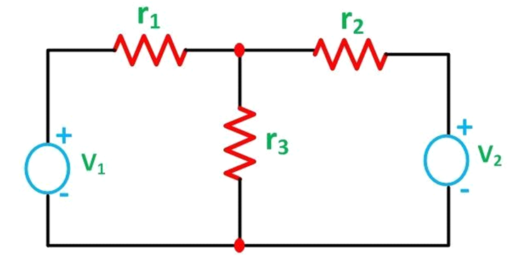
Let us understand the superposition theorem with the help of an example. The circuit diagram is shown below consists of two voltage sources V1 and V2.
First, take the source V1 alone and short circuit the V2 source as shown in the circuit diagram below:
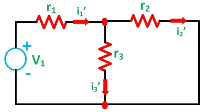
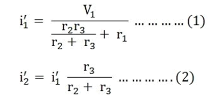
Here, the value of current flowing in each branch, i.e. i1', i2' and i3' is calculated by the following equations.
The difference between the above two equations gives the value of the current i3'.
i₃′ = i₁′ − i₂′......(3)
Now, activating the voltage source V2 and deactivating the voltage source V1 by short-circuiting it, find the various currents, i.e. i1'', i2'', i3'' flowing in the circuit diagram shown below
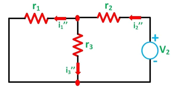
Here,
i₂″ = V₂ / [(r₁·r₃) / (r₁ + r₃) + r₂] ———(4)
and
i₁″ = i₂″ · (r₃ / (r₁ + r₃))———-(5)
And the value of the current i3'' will be calculated by the equation shown below:
i₃″ = i₂″ − i₁″———(6)
As per the superposition theorem, the value of current i1, i2, i3 is now calculated as:
i₃ = i₃′ + i₃″ ——(7)
i₂ = i₂′ − i₂″——(8)
i₁ = i₁′ − i₁″———(9)
The direction of the current should be taken care of while finding the current in the various branches.