
Step-up Chopper with R Load
Introduction
A step-up chopper, also known as a boost chopper, is a type of DC-DC converter used to increase the output voltage of a DC source. It is commonly employed in various power electronic applications to
boost the voltage level efficiently and is considered the counterpart of the step-down chopper, which reduces the output voltage.The step-up chopper operates based on the principle of energy storage and transfer.
It includes a switch (usually a semiconductor device such as a MOSFET or IGBT), an inductor, a diode, and a capacitor.
Working Principle of Step-up Chopper
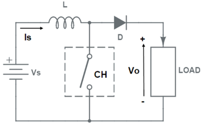
To understand the working principle, let us first have a look at an equivalent circuit diagram of step-up chopper. This is shown in Fig. 2. Chopper is shown as a switch CH. During the ON time of the switch, the inductor current increases, and energy is stored in the inductor. When the switch is turned OFF, the inductor releases the stored energy, and the output voltage is boosted through the diode and capacitor.
We will understand the working of this chopper in two steps: Switch ON period and Switch OFF period of chopper.
Switch ON Period: When chopper (CH) is switched ON, the current will flow through the closed path formed by supply source Vs, inductor L and chopper CH. During this period, no current will flow through the load. Only source current is will flow and the value of load current io will be ZERO during the ON period.
This case is depicted in figure below.
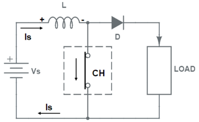
During the TON period, energy is stored in the inductor L. This energy storage in L is essential to boost the load output voltage above the source voltage. Therefore, a large value of L is required in a step-up chopper.
Switch OFF period: When the chopper CH is switched OFF, the current through the L can not die instantaneously rather it decays exponentially. Due to this behavior of L, it will force the current through the diode D and load for the entire time period TOFF. This is shown in figure below.
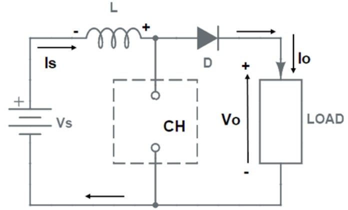
Since, the current through the inductor L tends to decrease, the polarity of the emf induced in inductor L is reversed as shown in above figure. As a result, the voltage across the load becomes equal to the sum of source voltage and emf induced in inductor. Thus, the output voltage exceeds the source voltage Vs. The load / output voltage may be written as below.
$$V_o = V_s + L\frac {di}{dt}....(1)$$
Thus, the circuit works as a step-up chopper. It may be noted here that, the voltage across the load increases because the inductor releases its stored energy to the load during the OFF period.
Analysis of Waveform:
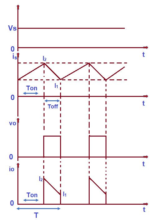
The first waveform represents the source voltage which is a DC voltage equal to Vs. Therefore, it is shown as a straight line parallel to time axis. Second waveform shows the source current is , When chopper (CH) is switched ON, the source current increases from its minimum value I1 to maximum value I2. It may also be noted that, this source current flows through the inductor during ON time. Therefore, it may be said that the current through the inductor L rises from I1 to I2 during ON period. During this time, no current flows through the load as shown in io versus time (t) graph.
When chopper is switched OFF, the source current starts decreasing from its peak value I2 to least value I1. Thus, the current through the inductor decreases from I2 to I1 during the OFF period. Since, load only comes into circuit during the OFF period, it may be said that, load current decreases from I2 to I1 during OFF time.
Calculation of Output Voltage:
From the above analysis of source current and load current waveform, it is clear that, the average value of current flowing through load and inductor
are same and equal to (I1 + I2)/2. The energy is stored in L during chopper ON time. This stored energy in L during the ON period is equal to the multiplication of voltage across the inductor, average current through it and TON time. The voltage drop across L during ON time equal to the source voltage Vs.
Energy stored in the inductor L is given by
= (Voltage across L)(Avg. current through L) * TON
$$= \frac {V_s(I_1+I_2)}{2} * T_{ON}....(2)$$
When chopper is switched OFF, the energy released by inductor to the load is given by
= (Voltage across L)(Avg. current through L) * TOFF
$$= (V_o-V_s) \frac {(I_1+I_2)}{2}*T_{OFF}....(3)$$
Considering the system to be lossless, these two energies given by equation (2) and (3) will be
$$V_s \frac {(I_1+I_2)}{2}*T_{ON} = (V_o-V_s) \frac {(I_1+I_2)}{2}*T_{OFF}....(4)$$
$$V_{s} * T_{ON} = V_{o} * T_{OFF} - V_{s} * T_{OFF}$$
$$V_{o} * T_{OFF} = V_{s}(T_{ON} - T_{OFF}) = V_{s} * T$$
$$V_o = V_s\frac {T}{T_{OFF}} = V_s*\frac {T}{T-T_{ON}}$$
$$V_{o} = V_{s}*\frac {1}{1-\alpha}....(5)$$
Advantages of Step-up Chopper
Voltage Boosting: The primary advantage of a step-up chopper is its ability to increase the output voltage from a lower level to a higher level efficiently. This feature makes it valuable in various applications where the input voltage is insufficient for the load requirements.
Efficiency: Step-up choppers can achieve high conversion efficiency, especially when operating in Continuous Conduction Mode (CCM). By storing and transferring energy through the inductor, the chopper minimizes energy losses during the conversion process.
Regulation and Control: Step-up choppers allow for precise regulation and control of the output voltage. By adjusting the duty cycle of the chopper's switch, the output voltage can be varied as needed to match the load requirements.
Disadvantages of Step-up Chopper
Higher Component Stress: In step-up choppers, the components, especially the switch and diode, experience higher voltage and current stresses compared to step-down choppers. This increased stress may require the use of components with higher voltage and current ratings, which can impact cost and design complexity.
Complexity: The control and regulation of step-up choppers can be more complex compared to step-down choppers. Achieving smooth regulation and reliable operation in both Continuous Conduction Mode (CCM) and Discontinuous Conduction Mode (DCM) may require sophisticated control strategies.
Electromagnetic Interference (EMI): Step-up choppers can produce higher levels of electromagnetic interference due to the faster switching of the components and the higher voltage stress. Proper filtering and shielding measures may be necessary to mitigate EMI effects and ensure compliance with electromagnetic compatibility (EMC) standards.
Applications of Step-up Chopper
DC-DC Voltage Boosting: It is used to increase the voltage level of DC power sources, such as batteries, to match the required voltage for specific loads or systems.
Photovoltaic (PV) Systems: In solar energy systems, step-up choppers are used to boost the output voltage from the PV panels to the required level for grid-tie inverters or battery charging.
Power Supplies: Step-up choppers are used in power supply circuits to provide higher output voltages for specific electronic devices or systems.
Electric Vehicle (EV) Charging: In EV charging stations, step-up choppers are employed to increase the voltage from the AC grid to the required charging voltage for the EV battery.