
Spice Code Platform
Steps to Complete the Code
Arrange the Code Blocks:
- Place the code block that defines the gate name, includes the model file, and declares parameters first.
- Next, add the code block that defines the voltage source.
- Then, add the block that defines the inverter subcircuit.
- Follow with the netlist statement that instantiates and calls the inverter subcircuit.
- Add the block that defines the input waveform 'a'.
- Add the control statements to run the circuit and plot the required graphs.
- Finally, add the end-of-code block.
Drag and Drop:
- Drag and drop the code blocks to arrange them in the order mentioned above.
Complete the Code Blocks:
Enter the name of the MOSFET model file to be included (
PTM_45nm.txt).For the voltage source, enter a name and select
vddas the positive terminal and0orgndas the negative terminal.Define the subcircuit by giving it a name and specifying the input and output arguments.
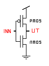
Inside the subcircuit block, connect the PMOS and NMOS as follows:
INSTANCE_NAME DRAIN GATE SOURCE BODY NAME_OF_MOSFET_AS_MENTIONED_IN_MODEL_FILE_INCLUDED w=WIDTH l=LENGTH- Give instance names to both NMOS and PMOS.
- Connect the drain ports of both MOSFETs to the output of the subcircuit, the gates to the input, and the source/body of PMOS to
vdd, and of NMOS togndor0.
Refer to the following circuit diagram for connections:
End the subcircuit block by typing the name of the subcircuit after
.ends.Call the inverter subcircuit by giving an instance name, then
aas input andoutas output, and complete the call by typing the inverter subcircuit name.
Note:
- While naming subcircuits, nodes, variables, and instance names, ensure they begin with an alphabet,
%,$, or_and only contain alphanumeric characters,%,$, and_. - The SPICE code is case-insensitive. Do not use the same name for any two variables in the same circuit or subcircuit, regardless of case.
Observations
- After clicking the Validate button (assuming all code blocks are filled correctly), you should see a "Success" message, a report, and input/output graphs under the Observations section.
- Observe the input waveform and the corresponding output waveform.