
Calculation of SINR including Beam Tilt: Downlink 
Theory
Introduction:
In a communication system especially while consider the physical layer are mainly concerned with signal to noise ratio. However when we look at a system with multipath users or multiple transmission going on simultaneously then usually we need to reuse the radio resource. This re-used radio resource causes co-channel interference to the undesired user.
In cellular system offers the carrier frequency is re used in order to increase capacity. This is explained in details later. So, while one transmitter uses a frequency say and another transmitter which is physically far away from the rest.
Transmitter is assigned the same frequency for transmits information to the target. Thus which one pair of Tx and Rx from the desired link the often Tx act as co-channel interference. This instead of consider only SINR as the metria it is more important to SINR in design of such system.
In cellular communication a carrier frequency is re-used to support a high number of users. Re-use of frequency means that the same frequency may be used simultaneously in two di erent cells for supporting two different active users at the same time. As a result of the simultaneous transmission on the same carrier frequency, interference occurs.
1.1 Downlink SINR:
If the Mobile Station (MS) is connected to the Base Station 1 ($BS_1$) and Base Station 2 ($BS_2$) is residing in co-channel cells, then, $BS_1$-MS is the desired link and $BS_2$-MS is the interfering link for downlink and vice-versa.
Considering the following,
$P_{T_x1}$ is the transmitted signal power from $BS_1$,
$P_{T_x2}$ is the transmitted signal power from $BS_2$,
$P_{R_x1}$ is the received signal power by MS from $BS_1$,
$P_{R_x2}$ is the received signal power by MS from $BS_2$,
$P_{N1}$ is the received noise power by the MS when it is connected to $BS_1$,
$P_{N2}$ is the received noise power by the MS when it is connected to $BS_2$,
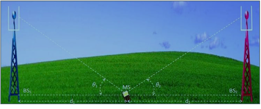
Figure 1. Illustration of Downlink SINR: $d_1$ is the straight line distance parallel to the earth crust between MS and $BS_1$. $d_2$ is the straight line distance parallel to the earth crust between MS and $BS_2$. $\theta_1$ is the angle of the transmission line between MS and $BS_1$ with the straight line between MS and $BS_1$ parallel to the earth crust. $\theta_2$ is the angle of the transmission line between MS and $BS_2$ with the straight line between MS and $BS_2$ parallel to the earth crust.
Usually $P_{R_x1}$, $P_{R_x2}$, $P_{N1}$, $P_{N2}$ are given in dBm. So, these parameters are converted into equivalent watt using the following formula:
$$|P|{\text{watt}} = 0.001 \times 10^{(|P|{\text{dBm}} / 10)}$$
After obtaining $P_{R_x1}$, $P_{R_x2}$, $P_{N1}$, $P_{N2}$ parameters in watt, $|SINR_1|{\text{watt}}$ and $|SINR_2|{\text{watt}}$ are calculated using the following formula:
$$|SINR_1|{\text{watt}} = \frac{P{R_x1}}{P_{R_x2} + P_{N1}}$$
$$|SINR_2|{\text{watt}} = \frac{P{R_x2}}{P_{R_x1} + P_{N2}}$$
Then the corresponding $|SINR_1|{\text{dB}}$ and $|SINR_2|{\text{dB}}$ are calculated using the following formula:
$$|SINR_1|{\text{dB}} = 10 \log{10}[SINR_1] \quad \text{and} \quad |SINR_2|{\text{dB}} = 10 \log{10}[SINR_2]$$
The above Downlink SINR calculation includes the effects of 2 Base Stations at the MS. Proceeding in a similar fashion, the effects of other Base Stations can be included in the Downlink SINR calculation for the MS as usually occur in practice for cellular architecture.