
Design the time sequence model from use case depicting the interaction of the objects.
Theory
Object Oriented Design
- Design helps in specifying the structure of how a software system will be written and function, without writing the complete implementation.
- It is a transition from "what" the system must do, to "how" the system will do it,
- Designing Classes:
- class identification from project spec / requirements
- nouns are potential classes, objects, fields
- verbs are potential methods or responsibilities of a class
- Use Unified Modelling Language(UML) to represent the classes and objects
- UML is an open standard; lots of companies use it
- UML is a descriptive language: rigid formal syntax (like programming)
- UML is a prescriptive language: shaped by usage and convention
- it's okay to omit things from UML diagrams if they aren't needed by team/supervisor/instructor
- class identification from project spec / requirements
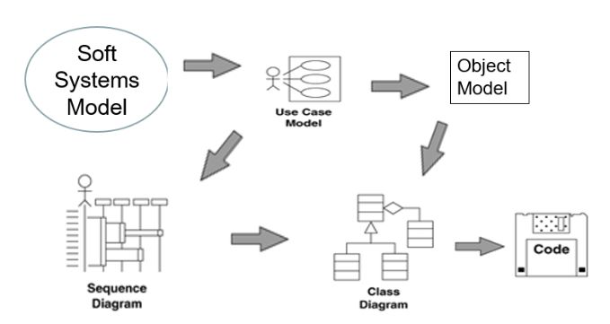
- Beginning of software system design is depicted in the following picture:
Time Sequence
- It describes the flow of messages, events, actions between objects.
- It shows concurrent processes and activations.
- It shows time sequences that are not easily depicted in other diagrams.
- It is typically used during analysis and design to document and understand the logical flow of your system
Sequence diagram emphasized on time ordering!
Sequence Diagram Key Parts:
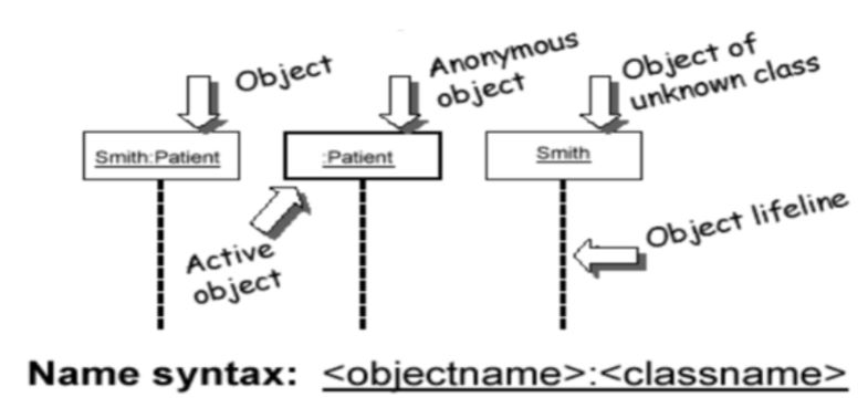
participant: an object or entity that acts in the sequence diagram.
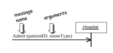
message: communication between participant objects
- Messages
- The name of the service requested by the calling object.
- Copies of the information required to execute the service and the name of a holder for the result of the service.
- In practice, messages are often implemented by procedure calls.
- Name = procedure name.
- Information = parameter list.
- Messages
the axes in a sequence diagram:
horizontal: which object/participant is acting.
- X-axis is objects.
- Object that initiates interaction is left most
- Object to the right are increasingly more subordinate
- X-axis is objects.
vertical: time (down implies forward in time)
- Y-axis is time
- Messages sent and received are ordered by time.
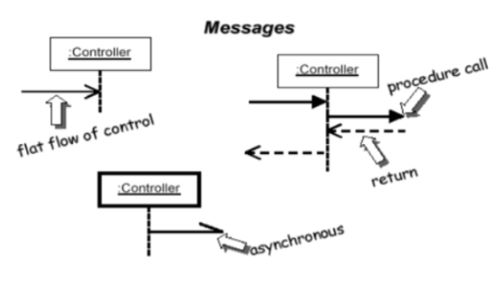
- Activation (double line) is the execution of the procedure
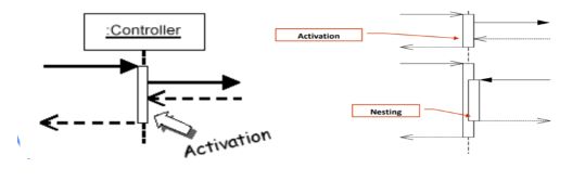
- Object lifelines represent the existence over a period of time
- Messages sent and received are ordered by time.
- Y-axis is time
Steps for Building a Sequence Diagram
- Identify which objects and actors will participate.
- Set the lifeline for each object/actor.
- Identify the messages from the use case.
- They are the verb phrases in the use case.
- Lay out the messages from the top to the bottom of the diagram based on the order in which they are sent.
- Add the focus of control for each objects or actor’s lifeline.
- Identify which objects and actors will participate.